

Introduction: Fusion 360 CAM for CNC Beginners


Fusion 360 is an awesome tool you can use with your CNC because you can do fancy cuts like 3D curves, slopes, and complex layers. BUT it can also be a little daunting. So we've put together this beginners guide to using Fusion 360 CAM for your CNC.
Before we dive in, here are a couple things to help you follow along. First, a link to the Fusion 360 3D file we're using so you can follow along/poke around:http://a360.co/2CE9Gwv
Second, here are time-stamps for the video for each section we're gonna cover:
0:37 Types of cuts
1:08 Process overview
2:00 CAM
2:29 CAM - setup
2:41 CAM - setup - stock tab (material)
3:14 CAM - setup - setup tab (orientation and zero)
4:07 CAM - tools
4:11 CAM - tools - cloud libraries
4:21 CAM - tools - add new tool
4:38 CAM - tools - speeds and feeds
5:21 CAM - toolpaths
5:39 CAM - toolpaths - passes we use
6:28 CAM - toolpaths - customize toolpath
6:36 CAM - toolpaths - customize toolpath - tool tab
6:43 CAM - toolpaths - customize toolpath - geometry tab
7:35 CAM - toolpaths - customize toolpath - heights tab
7:42 CAM - toolpaths - customize toolpath - passes tab
8:31 CAM - toolpaths - customize toolpath - linking tab
8:51 G-code
9:42 Machine Controller
9:58 Carve!
Lastly, this wasn't a sponsored project or anything, but we'll go ahead and link to Fusion and the CNCs we used in this video:
Carvey: https://goo.gl/Vh5mSt
X-Carve: https://goo.gl/dBvSAL
Fusion 360: http://autodesk.com/fusion360
Easel post processor - https://goo.gl/C9zF7F
Step 1: Types of Carving


First off we're gonna go over the different types of carving a CNC can do. Most common are outlines around a shape or flat surfaces at different depths.
You can make a lot of really cool stuff using just these types of cuts, but you can also carve more 3D looking shapes or do really complex designs with multiple flat surfaces, way more than you would wanna calculate manually.
These fancy cuts are big deal for a computer to do, but a computer doesn't know what's in your head, so we'll show you how to tell it what's in your head.
Step 2: Process Overview

- CAD: First you need a 3D CAD model of the thing you wanna carve. You can design one yourself or download existing models to use.
- CAM: Then you show the CNC how to carve this model from your stock material. This process is called CAM.
- G-code: Next you generate instructions that your CNC can understand.
- Machine controller: Then load these instructions into your machine control software, in this case Easel
- CNC: Click run and your CNC takes those instructions and starts carving.
So this video's about how to cut fancy things on your CNC, not how to model them in the first place, so we're gonna skip over CAD and save that tutorial for another time. But you can download our file and follow along, no 3D modeling experience required.
Step 3: CAM


This means we're jumping straight into CAM, which is the meatiest part of our tutorial. In order to explain all these steps, we're gonna show you how to make Kevin. Kevin is this little smiley face guy.
To get to the CAM portion of Fusion 360 click on the work space selector and then click CAM.
Step 4: CAM - Setup - Stock


In CAM, the setup is where you’ll define 1) what the raw material is, 2) how your model is oriented, and 3) what you wanna end up with.
You’ll start by clicking the setup drop down on the upper left and selecting new setup.
The setup window with a few tabs will pop up. We’ll start with the stock tab. Some people define their material, or stock, directly in the setup tab.
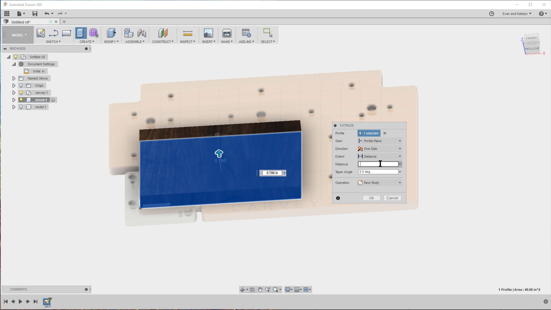
But we like to model the actual stock in CAD…
…and then define the stock from solid (on the stock tab) using the body we made.
This is nice because you can move your model around within the stock, see where it’s gonna end up, and regenerate your toolpaths later.
In this example, we’ll use a piece of walnut that’s 8 inches long, 5 inches wide, and 3/4 inches thick.
Step 5: CAM - Setup - Orientation


If your model is not oriented correctly, right click your setup on the left menu and click edit.
On the window that pops up, you can easily change your work coordinate system.
To orient your model correctly, click the top of the stock for the Z axis…
…and an edge for the X axis.
Then choose the origin from your stock box point, or model box point. The origin shows your machine what it should consider to be zero, aka it’s starting or home point.
Some machines auto home to a certain point, so you should set your origin to that location. For Carvey that is the top of your material in the bottom left corner.
But for a lot of other machines like the X-Carve you can set your home point almost anywhere. We pick a spot that makes sense for the model like the middle of the piece or a corner.
In general you wanna choose the top of your material as the home point. And that’s because if you pause, stop, or finish your carving, it will often try to return to home, and if your home’s set at the bottom, it’ll try to eat through the material to get there.
Step 6: CAM - Tool


Now that you’re done with the setup, we need to tell Fusion what tool you’re gonna use to cut.
But first, a quick tip for ya!
Make sure to enable your cloud library that way your tools, post processors, and other assets are easily shareable between computers. To enable it, click on your account drop down in the upper right, and choose preferences.
In the preferences video that pops up, click CAM on the left menu bar.
Then click the Enable Cloud Libraries check box.
Now we’re going to add your tool. First open up your tool library from the Manage menu on the top bar.
Then click on your cloud library on the left menu.
And click the icon on the top right to add a new mill tool.
Select the type of cutter, most likely a flat end mill.
And enter the dimensions of your tool, measuring with calipers.We like to also enter the speeds and feeds here so they’re saved in the cloud too.
The speed is how fast the bit rotates, but some machines won’t use this input, like the X-Carve.
So you can skip this step if you want. The Carvey’s speed can change, but in most cases you’ll wanna do 12,500 RPM since that’s the most efficient for the motor.
The cutting and plunge feedrates are probably the most important numbers here because they determine how quickly the bit moves through material.
These depend on your machine…
…material…
…and tool.
We actually use Easel to cheat on this. Easel will hold your hand walking through the setup of the materials and tools you’re using, it’s pretty quick and intuitive. After you’ve told it your setup, click on cut settings in the upper right menu it’ll tell you a feed rate, plunge rate, and depth per pass.
Step 7: CAM - Toolpaths


Next you define the toolpaths, which are the paths the tool is gonna take to cut your model out of the material.
This sounds daunting, but there’s preset options you can choose from and customize, you can quickly simulate cuts to see what each path does and see if there’s any errors, and you can even layer multiple paths.
First we’ll do an overview of some useful toolpaths, and then we’ll dive deep into one of them to show you how to customize them.
Step 8: CAM - Adaptive Clearing


The toolpath we usually start with is Adaptive Clearing.
This is essentially an easy button to rough out your shape from the stock as efficiently as possible. It makes room for your tool to do more detailed passes later. This could be used as the only operation or you can leave stock and finish it up in other operations.
Step 9: CAM - Parallel Passes

Parallel Passes are great for cleaning up rounded areas. We like doing two sets perpendicular to each other.
Step 10: CAM - Circular and Pocket Clearing

Things like Circular and Pocket clearing are great for cutting recessed areas out of your model.
Step 11: CAM - 2D Contour


Our final toolpath is usually a 2D Contour. This is a nice smooth last pass and it also has the option to add tabs!
These are great because they keep your final model in place when it’s being carved and they’re easy to remove once you’re done.
Step 12: CAM - Adaptive Clearing - Tools Tab


Any path you choose has further details you can customize. We'll dive into Adaptive Clearing options so you can see how to handle these details. Click Adaptive Clearing from the 3D menu across the top.
A window with several tabs across it pops up. You start in the Tool tab.
Click Select on the Tool section...
... and select the tool you defined earlier.
Notice that the feedrates entered earlier come with it.
Step 13: CAM - Adaptive Clearing - Geometry Tab
The Geometry tab defines what will be cut out of how much stock.
We choose an offset from the model to carve within the boundaries of...
...otherwise the machine thinks it should eat away literally all of your stock.
Under the Machining Boundary drop down, we usually select Silhouette which restricts the toolpath to a boundary around your part.
Then we add some additional offset larger than the diameter of your tool so it can fit all the way in.
If your offset is too small, the tool may not be able to reach where it needs to cut the model out.
Rest machining might need a little bit of an explanation.
It's basically asking where it should begin "machining the rest" of your model.
Step 14: CAM - Adaptive Clearing - Heights Tab

The Heights tab defines movements of the tool such as clearance and retraction, and the defaults are usually fine for basic toolpaths.
Step 15: CAM - Adaptive Clearing - Passes Tab


The Passes tab is very important. This is where you define how aggressive the depth of your cuts are, called out here as Stepdown.
Remember the depth per pass/depth per cut we referenced earlier that we grabbed from Easel? This is where you enter it.
You should also pay attention to the Stock to Leave option.
Picture this as a protective bubble of material around your model.
When you're doing curves and slopes and wanna layer additional finishing toolpaths after your Adaptive Clearing path, you need to leave a little bit of extra meat to cut into.
On the other hand, if you're doing just one operation to get your final product, you can leave this option unchecked. For this topographical Texas we made a while back, we liked the layered look left by just the Adaptive Clearing pass, so we left it unchecked.
But for Kevin, we wanted that protective bubble of stock so that we could do a 3D Parallel pass or two to finish with finer detail.
Step 16: CAM - Adaptive Clearing - Linking Tab


The Linking tab is probably only for advanced users and can be left at the default settings.
Click ok and watch your toolpath generate!
And now you can simulate your carving to get a preview of what you'll end up with.
Step 17: G-Code


Alright guys, you made it through the toughest steps. It's pretty easy from here.
To finish up, you need to select a post processor so that Fusion can export cutting directions, called G-code, in a way that your specific machine can understand.
So remember how we enabled Cloud Library earlier for our tools (the quick tip)? This also added an Asset Library where we can store CAM posts (aka post processors) between machines too.
We'll walk through how to add the post processor you need for your machine here. You can either post process the entire setup you created with all the layered toolpaths, or you can pick just one toolpath from your setup to post process. See the drop down on the left? It shows your setup and all the toolpaths within it.
We also have a photo above showing an example of just selecting one of the toolpaths.
When you're ready, right click on the setup, or specific toolpath, and click Post Process.
Then find the post processor for your machine, whether it's local or in the cloud (ours was in the cloud, so we selected Use Cloud Posts):
Select the post processor (Easel for the Carvey and X-Carve). You can download the easel post processor right here if you need it: https://goo.gl/C9zF7F
Then click Post!
Now you have some G-code, saved as a little .nc file on your computer.
Step 18: Machine Controller


Next open up the machine control software for your machine. This is Easel for the Carvey and X-Carve, but the process will be the same for any similar CNC machine.
Go to File > Import > G-code to import the G-code file and you'll see the toolpath show up.
Step 19: Carve! + Quick Tip


Click Carve in the upper right corner (the green button), go through the automatic prompts/checks, and you're good to go!
But if you're nervous about carving, we have another quick tip for ya.
If you wanna test your G-code before running it on expensive wood.
You can run it on cheap material or in the air.
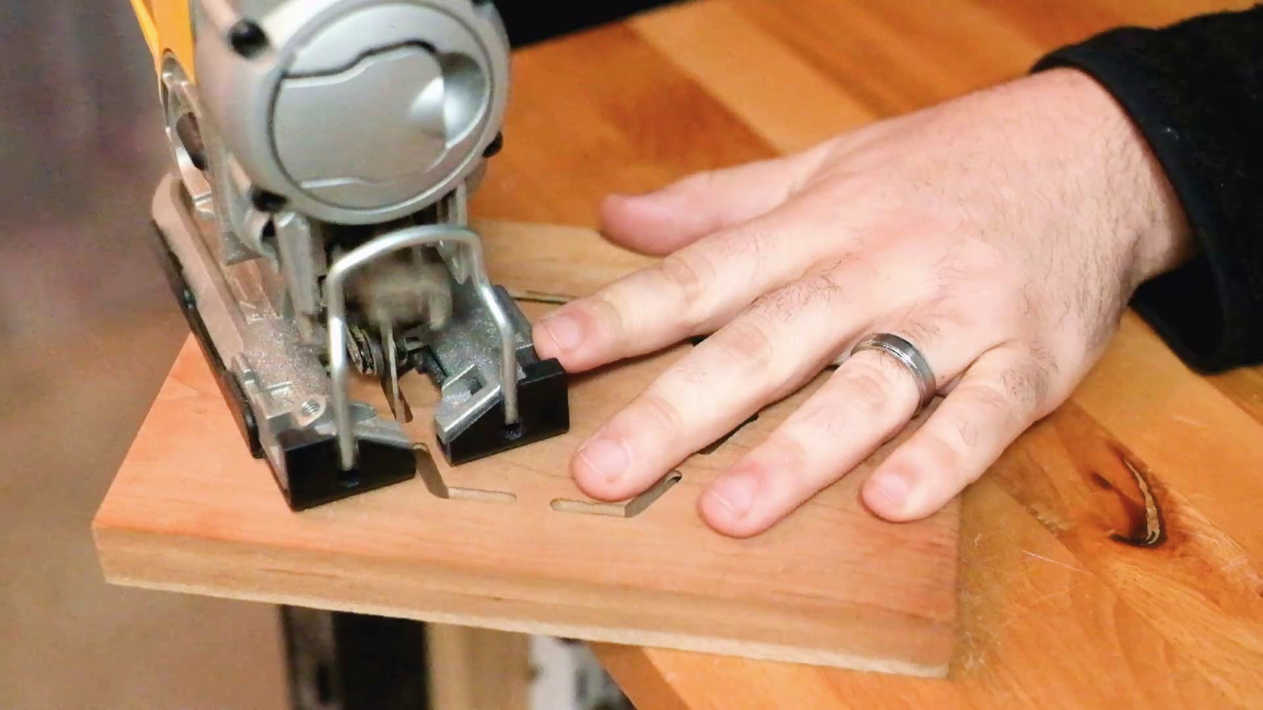
When your carving is done, remove the stock and cut any tabs necessary with a jigsaw and sand them down like we showed in the earlier photos.
So at this point we haven't sanded Kevin at all. And you can see how smooth the combination of toolpaths we did got the finished surface.
We gave him a quick sanding and an oil finish. It was really easy because the paths were really detailed passes!
Thanks so much for making it through this very information-dense tutorial with us! If you have any questions just let us know (we'll see them most on the the YouTube comments)
This was not a sponsored project and we did not get paid to do this, BUT we do have a Patreon account if you find value in what we do and want to support us - but no pressure! Thanks y'all!
………………………………………………………………
You can also find us at: YouTube (all our DIY videos) Instagram (sneak peeks @evanandkatelyn) Our website (includes tutorials from our pre-YouTube days) Pinterest (stuff that inspires us) Twitter (us, in 140 character doses) Facebook (be our friend)
………………………………………………………………
Note: This post contains affiliate links. Thank you for supporting us!


