

Introduction: GSM Arduino Latching Relay

Hello and welcome to my first instructable. I hope it's ok everyone!
Anyways, this instructable is about making a basic GSM latching relay.
The idea is simple enough, the phone is rung, and the output is turned on, the phone is rung again, and the output is turned off.
Obligatory Mains Electricity Warning
I should add at this point, that Mains Electricity is Dangerous, and can kill.
Never work on the internals of the project when the cover is removed and the unit is connected to mains as there will be live contacts exposed!
If in doubt, don’t' do it!
Step 1: Materials & Parts


To build this, you are going to need these items! :)
Shopping List
Project Box - eBay - "http://www.ebay.co.uk/itm/181618566372" - £4.99
Biggest size.
Arduino Uno - eBay - "http://www.ebay.co.uk/itm/111494292871" - £2.94
Yes it's not ideal to cheap out on the arduino but i wanted to keep costs to a minimum.
Arduino Relay - eBay -"http://www.ebay.co.uk/itm/281680894531" - £1.19
A smaller relay to connect the arduino to the mains relay.
Mains Relay - eBay - "http://www.ebay.co.uk/itm/190836816737" - £7.25
This one is rated 30A at 240V and is used to switch the high voltage on and off.
12V Power supply - eBay - http://www.ebay.co.uk/itm/190586320487 - £5.99
You don't have to use this one, any 12 volt supply will do, as long as it fits in the project box and can provide 2 amps or so.
5V Power supply - eBay - "http://www.ebay.co.uk/itm/151659818216" - £2.69
This is used to lower the 12 volt supply to the 5 volts needed to run the arduino and the arduino relay.
Mobile Phone
I used a LG KG800, they are cheap on ebay and easy to hack.
An alternative would be the Nokia 3310, which is also very easy to hack.
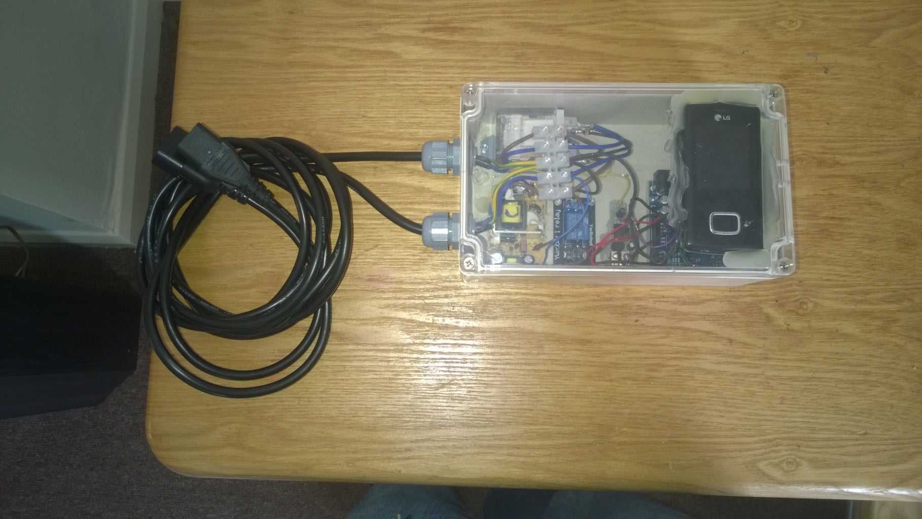
Step 2: The Plan

The photo shows the insides of the project, labelled.
Step 3: Wiring Diagram

This wiring diagram shows how I connected everything together to make the project work. Follow this and you should be fine.
Step 4: Mobile Phone Hacking


To be able to interface the mobile phone with the arduino, you are going to
need to hack your way into it, hardware wise anyway.
You will need access to the vibrator motor outputs and the battery contacts.
Vibrator Motor
On the LG I located the vibrator motor, which was connected using wires to the phone's motherboard. I cut off the motor, making sure that there was as much excess cable left behind to make soldering easier. I then soldered longer wires to these wires and covered the area in hot glue to help with cable strain and to hold my hack in place.
Nokia mobile phones, which is what I would personally recommend for this task are slightly harder though. You will need to remove the back plastic panel. This contains the vibrator motor. Remove the motor and solder wires carefully to the pads on the phone motherboard.
I have included a fault finding image of a Nokia 3310. This should aid in the location of the vibrator contacts.
When the phone receives an incoming call, a voltage appears on the wires.
You will need to experiment with this, figure out what the maximum voltage that appears is and the polarity of the wires. Connect the negative to ground.
Battery Contacts
Powering the phone is a little trickier as you cannot power the phone using the charging socket without the battery in place, and leaving the battery in place is impractical for many reasons.
I found that the easiest option is to remove the battery and connect power straight to the phone itself. However, some phone batteries have on board components which mean the phone will not start without the battery.
The LG required just 4 volts across its battery terminals to start up, all that was needed was a diode to drop the voltage only one volt or so from the 5 volt supply.
Nokia, however are more tricky, they require some extra work. There is a perfect explanation as to how to do connect an external supply on this website.
http://shaddack.twibright.com/projects/hw_nokiabat...
As again, solder wires to the battery terminals and cover in glue.
Step 5: Arduino Code

I hate coding. This part of the project took me the longest to get to work.
I was showed how to get this to work by my friend Seb at the Brighton Hackerspace. If you're in Brighton, drop by, say hello and you might even see me.
The code is attached. I have annotated it as best i can, but i'm still a lousy coder!
Attachments

Step 6: Adjustments
Depending on how the phone you use works, there are many thing you are going
to need to mod.
One thing I had to do was add an additional resistor across the vibrator motor outputs, as this dissipated a voltage that would appear and confuse the arduino as to what state it should be in.
Step 7: Finished Project


Finished!
See the Video to see the project in action
Step 8: Afterthoughts & Version 2
Afterthoughts
The phone still needs to be turned on, after the relay is pluged in.
The phone may vibrate for things other than an incomming call, and this will be seen as a input to the arduino.
Ideas for Version 2
Phone automatically turns on when the relay is plugged in.


