

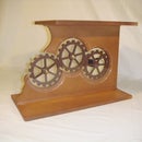
Introduction: Homemade Rotary/Flat Engraver


Materials & Supplies:
3/4" Plywood
Wood screws: 1-1/4" (20)
1/4-20 Hex-head nuts (15)
1/4-20 Washers (15)
1/4-20 3-1/2" Bolts (3)
1/4-20 2" Bolts (3)
2" U-Bolts (2)
1/4-20 Furniture Nuts (11)
3" Tee Hinge (2)
3" Barrel Hinge (2)
1" PVC pipe (Connecting flare end only)
1" PVC end cap
1/8 Plexi 8x10 sheet (1)
1/4 Plexi 8x10 sheet (1)
1-1/2"x3/4" Spring (a unistrut bolt from electrical supply will work)
1 6" zip tie
1 23/64"x1 3/8" compression spring
1 4" All-thread bolt (grind one end to create a point)
Tools:
Table saw
Screw gun
Craftsman Wrenches
Dremel
Epilog Laser Engraver/Cutter
1/2 Drill bit
3/8 Drill bit
1/4 Drill bit
Super glue
Measuring tape
Caliper
Pencil
Sandpaper (80/220 grit)
Grinder
Hammer
Vise
Band-aids
Aspirin
Step 1: Pre-cuts and Base Assembly


(Pre-cut materials for easier assembly):
Plywood:
- One 16"x22"x3/4" rectangle (Base)
- Two 2.75"x8"x3/4" blocks with 45 degree angle cut on one of the 8" sides (Base Track A and B)
- Two 2.75"x4.5"x3/4" blocks with 45 degree angle cut on one of the 4.5" sides (Base Track D.1 and D.2)
- One 4"x4"x3/4" block with 45 degree cuts on two of the sides (Base Track C)
- One 2.75"x3"x3/4" block (Tracer Arm)
- One 2"x7"x3/4" block (Main Slide)
- One 2.75"x14"x3/4" block (Main Arm)
- One 2.75"x6.5"x3/4" block (Spindle Arm)
- Two 2.75"x1"x3/4" blocks (Spindle Arm Spacer A and B)
- One 2"x7"x3/4" block (Spacer Arm)
Plexi:
- Two 2"x1"x1/8" blocks with half pipe cut outs (use 1" PVC pipe to measure)
- One .974"x1.31"x1/8" "C" shaped ring
- One 1.018"x.50"x1/8" ring
- One 3.25"x4.25"x1/4" block (with four drilled 3/8" holes in each corner)
Aluminum:
-One 1/16" thick Angled 3/4"x36" (cut down into two 10" pieces)
Base:
Take the 16"x22"x3/4" pre-cut board (noted above) and cut a 3/8"x6"x3/4" groove to allow a 1/4" bolt to slide up and down (start the groove 1" from the top of one of the 16" sides and center of board at 8")
Draw out and drill nine 3/8" holes to creat a 6"x6" grid in the middle of the board
Install the1/4"-20 furniture nuts to the back side of all nine holes.
Super glue the 1/4" washers on the front side of the board over all nine holes.
Step 2: Main Arm and Arm Support Assembly


Main Arm Support:
Take Base Track D.1 & D.2 and screw them together using wood screws ensuring the 45 degree angle cuts are lined up and on the outside.
Take Base Track C and drill 1/2" hole one inch from the top of block.
Line the tip of the 45 degree angle end of Track D with the undrilled end of Track C and attach using wood screws. This will create a 90 degree angle.
Attach Track C to the pre-cut groove in the base using a 1/4-20 2" bolt.
After attaching Track C to the base, attach Track Guides A & B to both sides of Track C using wood screws.
Main Arm:
Take the Main Arm (2.75"x14"x4" block) and cut a 3/8"x6" groove 1 1/2" center of block of the block starting 3" from the end.
Attach the Main Arm to Track D using a 3" Tee Hinge. Be sure to attach the hinge to the end of the Main Arm without the groove. Use wood screws to attach the hinge to Track D and 1/4-20 2" bolts to attach the Main Arm. Be sure to tighten the bolts using your Craftsman wrench.
Step 3: Slider, Spindle, Tracer, and Spacer Arms Assembly


Main Slider Arm:
Take the Main Slider Arm (2"x7"x3/4" block) and drill two3/8" holes 2.75" from each end and 1.25" from the top.
Install furniture nuts on one side of drilled holes (see photo)
Attach 2 1/2" barrell hinges to both ends of the Main Slider Arm using the screws that came with the hinges (see photo)
Spindle Arm:
Take the Spindle Are (2.75"x6.5"x3/4" block) and attach Spindle Arm Spacer "A" to one side using wood screws. Repeat with Spindle Arm Spacer "B" to the other side (see photo)
Take the Spindle Arm and attach to the Main Slider Arm at one of the hinges using wood screws (see photo)
Tracer Arm:
Holes 1 & 2:
Drill two holes for wood screws (1/8" drill bit) at one end of both aluminum arms. The first hole should be 3/4" from the end and the second hole should be about 1 3/4" from the first hole.
Hole 3:
Drill one hole 1/4" from the other end of both aluminum arms for the All-thread screw.
Hole 4:
Drill another 1/4" hole in both aluminum arms 3 1/4" from the end (same end as the third hole)
Take the Tracer Arm (2.75"x3"x3/4" block) and attach to the two pre-cut aluminum pieces by placing the block inside the angles of the aluminum. Drill wood screws through both the top and bottom to secure (see photo)
Take the All-thread bolt slide it through the top of hole #3 through the top aluminum arm. Thread on (in order) two bolts, washer, 23/64"x1 3/8" spring, second washer. Continue sliding All-thread bolt through hole #3 of bottom aluminum arm. Thread the top bolt about 3 1/4" onto the All-thread bolt. Double check that the tracer moves freely with the spring. This will be your Tracing Stylus.
Spacer Arm:
Take the Spacer Arm (2"x7"x3/4" block) and drill a 1/4" hole in the end though the top to the bottom to use it as a hinge.
To attach Spacer Arm to the Aluminum Tracer Arm take a 3"bolt and first slide it through the top of the top aluminum arm(see photo). Use a few 1/4" nuts on the inside of the aluminum arms to provide support. This will also allow the hinge to swing freely (see photo). To secure completely, continue sliding the bolt through the top of the bottom aluminum arm in hole #3. You can ajust as needed by tightening the bolts.
Next, attach the Tracer Arm to the Main Arm with a with Barrel Hinge (use screws that came with hinge)
Now attach the Spacer Arm to the Spindle Arm using a T-hinge (the T-hinge will need to bent to allow for proper movement (see photo)). To attach place the T-hinge on the inside of the Spacer Arm and on the outside of the Spindle Arm Spacer. Use wood screws.
Finally, attach the Spacer Arm to the Main Slider Arm by using a Barrel Hinge. Using wood screws attach the hinge to the outside Spacer Arm and to the inside of the Main Slider Arm.
Step 4: Dremel Mount Assembly


Assembly of Spindle Housing:
To create the housing, cut a 4" piece of the conneting end of a 1" PVC pipe
Take the 1" end cap and drill a 1/2" hole in the end of it (see photo)
Attach the end cap to the connecting end of the pipe and super glue them together (see photo)
Take the two half pipe plexi cut outs and rest the ends of PVC pipe/cap combo in the cut outs (glueing the plexi to the PVC is an option)
Next, take the two U-Bolts and place the plexi/PVC housing inside and securley tighten the bolts using your Craftsman wrenches. To avoid breaking the plexi, be sure not to over tighten the bolts (see photo)
Now take the housing unit and attach it to the Spindle Arm. To do so place the pre-cut plexi plate on the inside of the Spindle Arm and the housing unit on the outside of the Spindle Arm - thread on screws.
Step 5: Dremel Spindle Guide


Assembly of the Dremel Spindle Guide:
Remove the black guard off of the Dremel 4000.
Place pre-cut plexi ring over the Dremel head.
Reattach the black guard.
Place 1/2"x3/4" spring (from unistrut bolt) over the Dremel head (see photo)
Take the pre-cut "C" shaped plexi ring and slide it over the flexible shaft. Slide it over the bottom end of the Dremel and attach it to the grip useing a zip tie to hold in place (see photo)
Place the Dremel 4000 head into the housing unit.
Step 6: Engraving Operation


The Dremel assembly is the heart of the machine. It transmits reproductions of any template or master copy (type/art) by using the tracer guide method. The centering bracket permits the Dremel to be moved back and forth so that the Dremel can be positioned most advantageously above the item to be engraved. It consists of an adjustable ratio including the Slider Arm, Dremel Spindle,Tracing Stylus and the Centering Bracket. To adjust follow these steps:
-Unbolt the Main Slider Arm from the Main Arm, move it along the groove and rebolt. This will allow a change in font size.
-When moving the Main Slider Arm you must move the Spindle the same distance to ensure all three points line up (see photos)
Place the master type/art work on the center bottom of the base (under the Tracing Stylus). I recommend using 2-way tape to secure the placement.
Place engraving material in the center of the board. It is best to use a jig that will attach to the bolt grid.
Use your right hand to put the Tracing Stylus into the groove of the master copy and with your left hand depress the Dremel Spindle.
Before removing the engraved object from the jig/grid check that the engraving is complete. If not, retrace.
Highly polished metals such as glossy trophy brass should be masked off to protect the surrounding engraved areas from scratches.
IMPORTANT:
Never press down on the Dremel Spindel before the Tracing Stylus has been placed into the groove of the master copy type/art. The Dremel Spindel must always be relased before the Tracing Stylus is removed from the master copy and before it is transferred from letter to letter or shape to shape. The Dremel speed level will vary based on the material being engraved. Run a test to determine the speed.
Step 7: Mount Main Slide


Step 8: Free Hand Mastercopy/Text


This engraver allows alot of freedom from I.D'ing tools to making plaques amoung many other things.
I did go to many of my favorites places to find used parts. What I found was brass text and a few other things to help me with this project.
Here are a few photos of some engravings as well as some of the the homemade master copies.
First Prize in the
What Can You Do with a Dremel Tool?
Finalist in the
Craftsman Tools Contest
Participated in the
Epilog Challenge


