

Introduction: Honey, I Shrunk the Arduino: Moving From Arduino to ATtiny and Writing Your Code in Pure AVR-C

Arduino is a great hard- and software platform, but with all its features it is also a bit bloated and often you only need a small part of all the features. Sometimes your project requires to have smaller and cheaper devices. What you might need is the ATtiny microcontroller! For about $1 you can get for a example an ATtinyX5, a little 8-legged genius running at max. 20Mhz. This is totally sufficient for many projects and you can have a look a the size difference in the photo above. You can also have a look at this comparison chart to decide which ATtiny you need.
As others have already shown, you can easily program your ATtiny now using an Arduino and its IDE. But the problem with the code that is generated by the Arduino IDE is often that it is slow and large in terms of occupied flash memory. Since our ATtiny usually has only about 2K to 8KByte of flash memory, we need to be really careful about this.
To get full control about the code running on the chip it is recommended to write your programs in AVR-C, which is like C with modifications/extensions for the AVR platform.
This instructable shall show you how to write your first programs with AVR-C, transmit them to the microcontroller using a programmer and how to carefully debug your code by using the Arduino as serial-forwarder for the ATtiny.
What do you need?
- an ATtiny microcontroller. I used an ATtiny45 with 4KByte flash
- a programmer: For example the Adafruit USBtiny
- an Arduino for serial-forwarding (debug output)
- 1 breadboard
- 2 LEDs for testing
- 2 resistors (with about 150 Ohm or calculate here)
- some jumper wires
Step 1: Setting Up the Development Environment
Before we start writing any code, you need your tools set up and ready to use. In case of microcontroller programming, we need at least these things: A compiler and linker for our AVR-C code (avr-gcc), a standard-library (avr-libc) and a tool that transmits our program to the chip (called avrdude). Luckily, there are all-in-one solutions for this for AVR:
* For most Linuxes: Use the provided packages "avr-libc binutils-avr gcc-avr avrdude" in your package manager
* For OSX: AVR Crosspack
* For Windows: AVRStudio or AVR Toolchain for Windows
Make sure that you have the binaries in your PATH and then you can use them in your Terminal.
Step 2: Our First AVR-C Project: Hello World, LED!

Software
The "Hello World" of microcontroller programming is the blinking LED. So this is just what we'll try to achieve with our first program!
Please note: You can get the full code of these programs in my github-repository. It's also much better to view the source code there because github has proper syntax highlighting.
We don't want to do all the steps of compiling, linking, etc. by hand so the first thing we need is a Makefile. If you use AVR Crosspack on OSX, you can use the avr-project command in the Terminal which automatically creates a Makefile for us (and an XCode project that we don't need so you can delete it). Otherwise, you can use the following template for your Makefile. Please notice that you should modify the first lines of this template for your own setup (i.e. set the DEVICE and PROGRAMMER variables).
--
#
# Makefile template for ATtiny45
# Derived from AVR Crosspack template
#
DEVICE = attiny45 # See avr-help for all possible devices
CLOCK = 1000000 # 1Mhz
PROGRAMMER = -c usbtiny -P usb # For using Adafruit USBtiny
OBJECTS = main.o # Add more objects for each .c file here
FUSES = -U lfuse:w:0x62:m -U hfuse:w:0xdf:m -U efuse:w:0xff:m # settings as taken from http://www.engbedded.com/fusecalc/
AVRDUDE = avrdude $(PROGRAMMER) -p $(DEVICE)
COMPILE = avr-gcc -Wall -Os -DF_CPU=$(CLOCK) -mmcu=$(DEVICE)
# symbolic targets:
all: main.hex
.c.o:
$(COMPILE) -c $< -o $@
.S.o:
$(COMPILE) -x assembler-with-cpp -c $< -o $@
.c.s:
$(COMPILE) -S $< -o $@
flash: all
$(AVRDUDE) -U flash:w:main.hex:i
fuse:
$(AVRDUDE) $(FUSES)
install: flash fuse
# if you use a bootloader, change the command below appropriately:
load: all
bootloadHID main.hex
clean:
rm -f main.hex main.elf $(OBJECTS)
# file targets:
main.elf: $(OBJECTS)
$(COMPILE) -o main.elf $(OBJECTS)
main.hex: main.elf
rm -f main.hex
avr-objcopy -j .text -j .data -O ihex main.elf main.hex
avr-size --format=avr --mcu=$(DEVICE) main.elf
# If you have an EEPROM section, you must also create a hex file for the
# EEPROM and add it to the "flash" target.
# Targets for code debugging and analysis:
disasm: main.elf
avr-objdump -d main.elf
cpp:
$(COMPILE) -E main.c
--
You may wonder, what's this "FUSES" thing? While programming your microcontroller with a programmer it will set some bits in the chip which are some kind of initial configuration. Use this calculator for setting the right bits. With this configuration you can for example tell the microcontroller to use the RESET pin as normal I/O pin (which is helpfull when you have only 8 pins!).
Next, you need a minimal main.c-file which looks like this:
--
#include <avr/io.h>
int main(void) {
for(;;){
// main loop
}
return 0; // never reached
}
--
This program does actually nothing, but let's try to compile it nevertheless. Type make in the terminal and it will compile and link the programm. It even shows you the size of your program and how much it will occupy on the device.
make will call the all target of your Makefile. There are other important targets in your Makefile:
- clean will delete all generated binary files and let you compile them all anew
- install will transmit your program to the microcontroller using a programmer. more about that later
Now lets step by step create a full program for letting two LEDs blink in turn:
At first, we need to include some headers for common AVR-C functions. We already included avr/io.h for I/O handling, which means reading and writing from/to our pins. We'll also need a "delay" function because we want the LEDs to blink for a specified time. This function is included in util/delay.h. Next we define our pins that we use and the delay time. So the first lines of our program look like this:
--
#include <avr/io.h>
#include <util/delay.h>
// Define pins
#define PIN_LED1 PB0
#define PIN_LED2 PB1
// Define the delay time in ms
#define DELAY_MS 500
--
We need some helper macros and functions that we use often (in the future). In AVR-C, you set "high" to a specific pin, by writing a "1" bit to a specific port register using bitwise operations. In our ATtiny, we only have "PORTB" as I/O-port. When we want to set a pin "PB0" to "high" we would write: PORTB |= (1<<PB0);
Setting it to "low" works likewise with a bitwise operation by setting the bit at this position to "0" (LOGICAL-NOT 1): PORTB &= ~(1<<PB0);
We use this information to write two macros for setting a pin on a certain port "low" or "high". We furthermore define a function that allows us to create long delay times. The problem with long delay times is, that the internal timer (or clock-counter) register will overflow very fast because it is usually only an 8-bit counter. Therefore, we define a function that splits our delay into 10ms chunks and we wait X times 10ms for getting the long delay.
--
// write digital "high" to pin <pn> on port <prt>
#define DIGIWRITE_H(prt, pn) prt |= (1<<pn)
// write digital "low" to pin <pn> on port <prt>
#define DIGIWRITE_L(prt, pn) prt &= ~(1<<pn)
// Define long delay function
void long_delay_ms(uint16_t ms) {
for(ms /= 10; ms>0; ms--) _delay_ms(10);
}
--
Now let's advance to our main() function. At first, we will need to modify the "data direction register" for port B, which is set in the variable DDRB. This register tells the chip, which pins can get input data and which pins shall produce an output voltage. By default, all pins are set to "input". When we want to set certain pins to "output" we need to set their register bit to "1"
The rest is quite easy: We now only call DIGIWRITE_L() and DIGIWRITE_H() for the respective pins and alternate the status by using a variable toggle. Afterwards we add a delay time.
Notice the use of uint8_t for the toggle variable. When writing code for chips with very a small amount of flash memory, it is crucial to always use the smallest possible data type. You can change it to, for example, int32_t and you'll see that the memory consumption slightly rises.
This is the full code for our main loop:
--
// program entry point
int main(void) {
// DDRB is the "data direction register" for port B
// the ATtinyX5 only has port B with usable pins
// we set both LED pins to "output"
DDRB |= (1 << PIN_LED1) | (1 << PIN_LED2);
// initially set the pins to "low"
DIGIWRITE_L(PORTB, PIN_LED1);
DIGIWRITE_L(PORTB, PIN_LED2);
// main loop
uint8_t toggle = 0;
for(;;){
// alternate between the LEDs to let them blink
DIGIWRITE_L(PORTB, (toggle == 0 ? PIN_LED1 : PIN_LED2));
DIGIWRITE_H(PORTB, (toggle == 0 ? PIN_LED2 : PIN_LED1));
// alternave the toggle variable
toggle = !toggle;
// make a long delay
long_delay_ms(DELAY_MS);
}
return 0; /* never reached */
}
--
Type make to compile the code. It will generate a .hex-file. In the next step, I'll explain how we upload this to our ATtiny.
Step 3: Hardware Setup for Transmitting Your Program to the ATtiny

Now comes a crucial point. We want to transmit our program to the microcontroller. We do so by using a so called in-system-programmer (ISP) who will write our compiled .hex-file to the chip, set the fuse bits, check the whole stuff and so on. But don't panic, basically it will just boil down to a little bit of wiring and one command in the terminal.
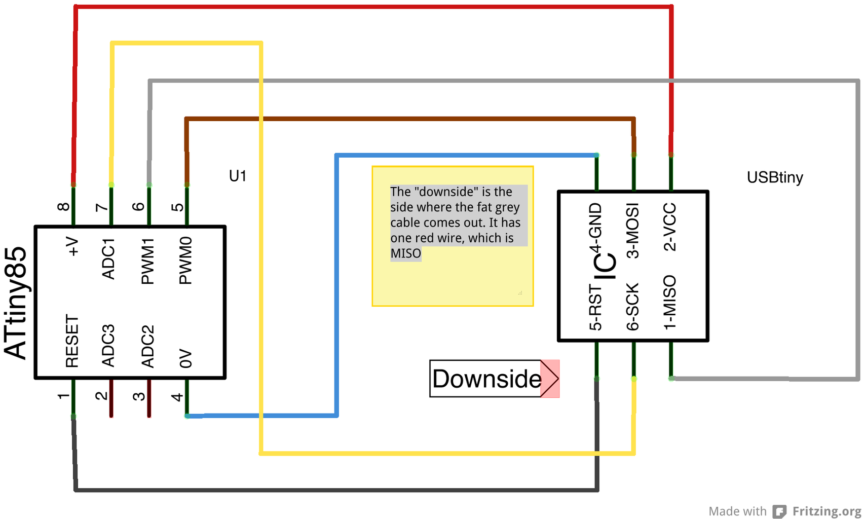
If you don't own an AVR target board or want to solder it yourself, we need to do the wiring. Take a breadboard and put your microcontroller there. Place it so that the very tiny spot indicating the RESET pin is in the lower left. Now take your ISP (and don't connect it to your computer, yet!). It has a cable with a 6-pin adapter. You'll need to identify port 1 (MISO). The side where the grey cable comes out of the adapter is the downside and on the right it is marked with a red wire. This indicates that the lower right is the MISO port. Connect it with pin 6 of your ATtiny. Now do the rest of the wiring as indicated in the schematics. Please note that you'll need to take great care when doing the wiring. So double check it, before you power up the ISP or your ATtiny can go up in smoke!
Now you're ready to connect your ISP with your computer. The next step is to call avrdude to upload your program to the chip. We'll do so by simply issuing the command make install in the terminal. If you've set the right ISP in your Makefile and have a proper wiring, it should transmit your program in a few seconds.
Step 4: Wiring Up Our LED Project

This is very simple setup. You just need to connect pin 5 (PB0) and 6 (PB1) of your ATtiny with an LED respectively (of course you need to add a resistor with at least 150 Ohm before). Then connect your chip with a power supply. The ATtiny works with 2.7V to 5.5V (depending on which model you have) so with 3.3V you should be fine. If you don't have anything like that in hands, just abuse your Arduino as power supply as shown in the schemes.
Now you should see our LEDs blinking! If you have a red and a blue LED it looks like police lights...
We got our ATtiny running but if you have more complex programs running on it, it will become extremely annoying to test your programs because the only option for "debugging" you have by now are some LEDs. In the next steps you will learn how to use a library called "softuart" in conjunction with your Arduino, which lets the ATtiny talk to a serial monitor in your computer.
Step 5: Making the ATtiny Talk to You

We already successfully created a small project but you'll notice that our ATtiny behaves a bit like a black box: You don't know really wants going on in it, because the only output you have are some LEDs. If you have a more complex program running, you might want to know want is going on in your chip, for example what values it is reading when doing anlog measurements. There are expensive development and debugging boards available but I will show you how can implement some basic "debugging" in a cheaper way.
In the case of the Arduino, you can have a serial connection to your computer and monitor values using the Serial Monitor. Unfortunately our ATtiny doesn't have such capabilities built-in because it is missing a FTDI chip for serial communication. BUT we don't have to be sad about that: We can implement software-based serial communication on our ATtiny and "abuse" our Arduino as serial forwarder. This means we can have the ATtiny talking to us through the Arduino (and the other way around if we need that).
Fortunately, we don't have to implement this on ourself since Martin Thomas and Colin Gittins made a nice library and put it on github: avr-softuart. We will use this to create a small program for our ATtiny that will transmit some test values via serial forwarding to our computer using our Arduino. You can use this later on in your own program for some basic "debugging".
A word of warning: "softuart" implements UART capabilities in software which means it is much slower than hardware-implemented UART. It also means that your ATtiny has to do some heavy lifting while handling the serial communication. Therefore I recommend using "softuart" only while debugging your project.
Let's start with our program for the ATtiny. At first we will need to download the avr-softuart sources from the github repository. We will need the following includes:
--
#include <avr/io.h>
#include <avr/interrupt.h>
#include <util/delay.h>
#include "softuart.h"
--
In the fie softuart.h you should set the SOFTUART_TXBIT in line 18 to the correct pin (in our example we set it to PB1). In the main loop, we start serial communication with the following instructions:
--
softuart_init();
softuart_turn_rx_off(); // we don't receive serial data
sei(); // this enables interupts, which are needed for softuart
--
The rest is quite easy. For example, if you want to transmit a character you can call softuart_putchar('c'); which will transmit the character 'c'. You can also transmit strings and, if you include stdio.h, you can also send printf-formatted numbers. You can have a look at the examples in main.c of softuart's github repository.
However, I recommend keeping it as simple, small and fast as possible. This means you should not include stdio.h and use printf() since it will take up about 1.5kB of your flash memory. Therefore you should implement a function that sends integers as character strings. I've done so in the second example for this tutorial and you can get the full code in the github repository. The program just writes integers between -128 and 127 to serial out. You can download, compile and upload the code to your ATtiny.
Now that we have our "talking" program on the ATtiny, we need to prepare the Arduino to receive this serial data and forward it via USB to our computer so that we can read the output on a serial monitor. The code is really simple and you should download it also from the github repository. It only receives incoming serial data with software serial from a certain pin (10) with a baud rate of 2400 (slow software serial!) and transmits it to our computer via hardware serial with a baud rate of 115200 (fast USB!). Upload this code to your Arduino and you can continue with the really simple wiring scheme above to put together the whole thing.
When you plug in your Arduino to your USB port, the ATtiny will start sending the serial data to the Arduino, which will forward it to our computer. Now you can use the Serial Monitor in the Arduino IDE or programs like screen or minicom to read the output. This enables you to see what's going in your ATtiny using just 1 pin and an Arduino!
I hope this tutorial will help you creating smart ATtiny programs that are using up just a fraction of the space and energy needed by an Arduino. You can have a look at the following project for an example about how to read analog sensor data from an accelerometer to detect when a device has been shaken: attiny-soundcube


