

Introduction: Hot Water Solar Collector Controller With Thermostat V1.0


The collector is controlled very simply – the temperature measured by the collector and the water heating tank (boiler). When the water temperature in the solar collector is higher than boiler, controller turns on the pump and the heat transfer from the collector to hot water storage begins. When the temperature difference decreases, the circulation pump is turned off. Controller described here, works as follows:
When the temperature difference between the solar collector and the tank more than 5 degrees, the switch is turned on. Temperture is measured and displayed on the screen constantly, but the difference is checked every 15 seconds.
When the temperature difference between the solar collector and the tank is less than 2 degrees, the relay is switched off. Difference checked every 15 seundžių.
Potentiometer can ask any number from 0 to 100, it rodomasekrane. When the 3-ber sensor temperature reaches the limit switches 2nd relay. Temperature falls below the limit switch turns off.
Instead of the two sensors (solder the two resistors or cut the track plate) can connect another 2-channel relay module and the necessary sensors connected sequentially on a single cable. For the controller to work after such changes require minimal improvements to the program.
DS18B20 sensors can be connected 2 or 3 wires.
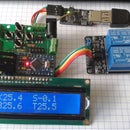
The display shows the boiler temperature, collector temperature, temperature difference, 3-ber temperature sensor, potentiometer preset temperature, relay status.
Step 1:
Step 2: Runing Test Version
Runing test version
Step 3: PCB
PCB
Step 4: Scheme
scheme
Step 5: Soldered Controller Details
soldered controller details
Step 6: Software
Here is the .pde sketch file
Attachments

Step 7: Lcd View
Screen model explanation: K44, 62 - the collector temperature 44.62 degrees,B34, 52 - boiler temperature is 34.52 degrees, S10, 20 - the collector temperature is higher than the boiler 10.20 degrees, a pointer to the top of the first row shows the pump control switch is turned on. In the second row the number 28 is a potentiometer set temperature value. 20.15 is a third temperature sensor value. Among these figures, the arrow down to show that the second switch is turned off, because the measured temperature is lower than set.The controller display
Part list:
Arduino pro mini 328
LCD 1602
2-Channel 5V Relay Module With Optocoupler For Arduino
3X DS18B20
10K Ohms 3296 trimmer potentiometer pot resistor
3x Screw Terminal Block Connector 3 Pins 5mm
Project web page http://www.saulevire.lt/en

Participated in the
Instructables Green Design Contest


