

Introduction: How to Build a Bi-Fuel (LPG & Unleaded) Trip Computer Using Arduino


The main reason I made this project is the lack of a trip computer that is designed for LPG powered cars.
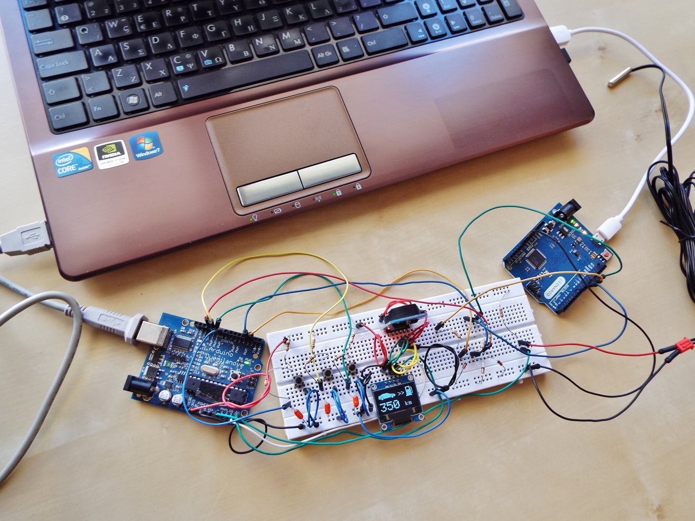
I named it Bi-TripCo as it can measure the fuel consumption for both fuel systems of a Bi-Fuel car (LPG and Unleaded). (for a detailed view see the embedded video of step 9)
Some might say: "I can buy one from the market" or "ok, a similar one, no big deal!". Don't rush.There are many (or some) tools out there, that can calculate the consumption of conventional fuel systems, which are very easy to use: just plug it into the OBD port of your car - unless you have an older car which does not have one, like mine. And, of course, there are some very good implementations based on Arduino, which can calculate many things related to the Unleaded fuel consumption.
But those tools can not be used on an LPG powered car (not to mention the relatively high cost of some of them).
Not only, they are useless for an LPG system, but they also give wrong readings (or no readings at all) related to the petrol system. Even, the already installed trip computer on a modern car becomes useless, as soon as an LPG system is installed.
Therefore, this system is not only useful for older vehicles but also for new ones, with an installed LPG system and it is universal.
An LPG ECU produces different signals to drive the LPG injectors from the ones that the car ECU produces to drive the petrol injectors (see step 3). For that reason, the part of the code concerning the measurement of the LPG consumption differs from the one that concerns the gasoline (or petrol...? :-) ).
I am giving you 2 versions of the code (step 8): One with metric units (l/100km etc. see the last animated .gif above) and one with imperial/US units (MPG, MPH, Fahrenheit etc. see the 1st animated .gif above).
Bi-TripCo tested many times throughout the last months and found to be way too accurate. The error does not exceed 0.8% for the total amount of the LPG litres consumed, of which the correct measurement is the main requirement (In fact the last time I test it for about 1500km the error was ~0,02%!!!!! The trip computer measured 111,3lt of LPG and I filled up 111,32lt in total!!!)
Finally, there are parts in the code and the schematic that are useful to other projects too, like:
- long (press and hold) and short button press
- RTC time setting with external buttons
- thermometer using a thermistor
- ATmega328 timer interrupts
- EEPROM read and write
- use of an OLED display
- external interrupts (more than the usual 2)
- Hardware Debouncing buttons (see the schematic at step 8)
At this project is also implemented a clock (RTC) and a thermometer using an NTC thermistor.
- As I have seen so far, no one of those who built a similar system does not give all the information you want to build it by yourself. For this reason, there are detailed steps with pictures and comments where needed.
- Also, there are many comments in the code files, in order to understand what I am doing every time. I hope you will find them helpful and also useful for other projects too.
- Finally, as you will notice there are many steps. This should not disappoint you if you plan to build such a system which, as you will see, it is relatively simple (see the schematic and you will understand what I mean).
This project was not easy for me too. When I firstly began to build it (almost a year ago), I knew basic things about Arduino. But after countless hours of searching, reading, studying, testing and of course failing ... I managed to build something. My first attempt was this one. Nice, isn't it! :-) Nevertheless, it worked good enough. I started to think which would be the best way to install it on my car and finally I ended with the one that I present you. I hope you will agree that it is a nice work and well adapted to the car. Certainly there is enough room for development and improvements...
After that, Instructables appeared. I thought that it was a good opportunity to share my work with other people. I believe that it is a good thing to share our ideas over the internet, as many competent people, with passion for their work, are doing. Thanks to them I managed to build this project and now I am very happy to introduce my work. Only this way we can become better and move forward. And Instructables is a good place to start...
Step 1: What You Will Need...


The things that you will need are:
- Arduino Uno board or compatible...(I use an Arduino Duemilanove only as a programming board which is the same with Arduino UNO)
- +Optional: 2nd Arduino Uno for testing at home (I used as a second one a Leonardo...).
Components:
- Atmel ATMEGA328P-PU microcontroller with Arduino Uno bootloader, 16MHz crystal + 28 pin DIP socket
- DS3231 RTC IIC(real time clock module) -(please read step 5 for some modifications you have to make at this module in order to work properly) - do not use the DS1307, is useless.
- 0.96" OLED Display module(you can use your preferred display with some easy modifications in the code - I used this one because it fits well at the dashboard of my car)
- Voltage regulator LM7805 or MCP1702-5002 LDO Low Quiecent Current Regulator (it's a little more expensive but it is better for the life of your car's battery - while it is not running of course)
- 10kohm NTC thermistor
- 5.1V zener diodes (x4 - easy to find at a local store or ebay)
- Resistors (local store or ebay)
10kOhm (x6), 47kOhm (x1), 100kOhm (x2), 10MOmh(x1), - Capacitors (local store or ebay)
Ceramic: 22pF (x2) -- MKT: 47nF (x2), 10nF (x1) -- Electrolytic: 10uF (x1), 1uF (x1) - Push Buttons (x2) - (local store or ebay) like this one or this one or... depends on where you want to put the buttons and what you prefer -- buy some more if you want to test it on a breadboard
- Prototype PCB - something like this one is enough or buy a bigger one and cut it to the preferred size (or you can build a PCB if you have the ability but it is not necessary)
- Cable wire connectors like this or this or what suits best for you (they give you the ability to take off the trip computer from the car and make changes to the program)
Electric wires, long enough to make the necessary connections
Tools:
- Multimeter (helps to find the signals we need from the car and make and make some basic measurements)
- Wire cutter or striper
- Soldering iron, wire and paste
- Isolating tape or heat-shrink tubes
- Optional: Breadboard and connection wires if you want to make some tests or to play around before you build the entire circuit.
Software:
- Arduino IDE
- Notepad++ (code editor)
- LCD Assistant (helps to display our own graphics on the screen)
As you can see the components are quite cheap.
The total cost can be kept easily below $15 (without the Arduino Uno and of course the tools).
Step 2: Principles of Operation and Signals Needed From the Car


1st signal: Injector driving signal
The total amount of fuel that an injector flows is proportional to the time that the injector is open.*
So, in order to calculate the fuel litres consumed we have to measure the time that the fuel injectors open. Then, using a coefficient, we can correspond that time to how much fuel the injector flows. We don't need to record the total time from all the fuel injectors. The signal (see the first picture above) from one of them is all we need.
The measurement of the total opening time of all 4 injectors is not only complicated, but it is also useless, because the total time is 4x the time that one injector opens. The factor 4x can be put in the coefficient that we mention above.
Mathematically we can write:
Litres of fuel burnt = Total milliseconds that an injector open X some coefficient (in litres/ms)
Don't bother about the coefficient. It is not so difficult to find it.(Step 10: Calibration... will help you on this)
(Everything mentioned above are applicable both for LPG and petrol. See next step for a difference between the signals for the one and the other fuel system)
You can find the corresponding wires easily at the engine compartment. Is the wires that go to the injectors connectors. See step 4.
2nd Signal: Speed Sensor
The second signal we need is from the speed sensor (2nd picture) of the car (known as vehicle speed sensor - VSS). This sensor produces pulses every specific distance. So, measuring the pulses and multiplied them with the distance travelled per pulse, we can calculate the total distance travelled.
Mathematically:
Distance = "Pulses from VSS" x "Distance between pulses"
See step 4 in which you can find info on how you can find the VSS signal.
3rd Signal: Ignition signal
The third signal is from the ignition switch. This signal is needed in order to put the trip computer and the display in sleep mode so as not to consume current while the car is parked.(see again step 4)
So, with the gasoline injector signal we must do 7 external connections in total:
- LPG injector driving signal (see step 4)
- Petrol injector driving signal (see step 4)
- VSS signal (see step 5)
- ignition signal
- 12V - battery voltage
- GND
- 1 connection for the thermistor (the other terminal of the thermistor goes to the chassis of the car - ground)
That's all...
(* that is not exactly true but for this project it seems to work quite well.)
Step 3: How an LPG Works + Driving Signals for LPG and Gasoline Injector and a "problem"...


(You can skip this step if you want, but I suggest to read it...)
In the picture 1 above you can see a simplified diagram of how an LPG system is installed and how the injectors work.
At first, lets see how the car ECU controls the petrol injectors:
The two terminals of the injector is the terminals of a coil. The one terminal of the injector is constantly connected to 12V. The second terminal is controlled by the ECU. When the injector is closed the second terminal is open and if you measure the voltage at this terminal you will find 12V. The injector opens when the ECU grounds this second terminal (current flows through the coil) for the amount of time needed (some ms every time) and the voltage will be 0V. So, when the voltage is 0V at the second terminal of the injector, the injector is open, and gas is flowing through it. The driving signal for the petrol injector is like the one at the 2nd picture above. The 3rd picture shows the signal that my car's ECU produces to drive the petrol injectors.
LPG injector:
As you can see (1st Picture above) the LPG ECU is interposed to this second terminal of the petrol injector (the wire of which is cut). With this connection the LPG ECU determines the time that petrol ECU "wants" to open the petrol injector and grounds the LPG injector for the correct amount of time.
LPG injector opening time = Petrol injector opening time X some coefficient, which is not constant and is related to the revs of the engine and in some degree to the temperature of the gas.
The problem...*
This is the main difference that I mentioned in the intro.
As you can see from the measurements (pictures 3, 4, 5 and 6) the driving signal of the LPG injector is not clear as the one for petrol injector. That's why the part of the code that records the time that LPG injector is open is different and more complicated than that for the petrol injector opening time.
Idea behind the part of the code that records the LPG injector opening time:
We always record the time a change occurs at the LPG injector signal.
We have 2 variables for this: injTime1 and injTime2
injTime2 is the time of the current change of the signal
injTime1 is the time of the previous change of the signal
We make the calculation (injTime2 - injTime1).
This interval can not be bigger than the duration of the first LOW (picture 4) which appears each time the injector opens.
So, we check that and if it's bigger we don not take it into account. (If it is bigger this means that this is the long HIGH between 2 subsequent LPG injector openings).
If the (injTime2 - injTime1) is within the acceptable interval limits we add it to the previous one.
Also we have a down limit (8us) for noise cancelling.
Below is the part of the code that is just described (see .ino file for more comments):
this is called every time a change occurs to the LPG injector signal
void LPG_injector_time()
{
injTime2 = micros(); //records the time a change occurs at the LPG injector signal
//check if the (currentTime - preciousTime) is within the limits
if ((injTime2 - injTime1)<6000 && (injTime2 - injTime1)> 8) //6000 can be less than that
{ LPG_injector_open_duration = LPG_injector_open_duration + injTime2 - injTime1;
//this is for 1sec interval. Every second we calculate the amount of LPG burnt using a coefficient (litres/us or gal/us) and then we reset the "LPG_injector_open_duration" variable to zero. This is useful for the instant consumption.
}
injTime1 = injTime2; // hold the current time that a change occurs in order to use it at the next time a change occurs.
}
After this we calculate the Total LPG used with the following formula:
used_LPG = used_LPG + (LPG_injector_open_duration * LPG_injector_flow);
LPG_injector_flow is the coefficient we mention above and we can set it while the system is installed at the car.
This gives us the ability to make the calibration more easily.
(*Ok, this is not really a problem. This is how low impedance injectors work, as I found then. But the first time I saw it, it didn't do good impression to me!!!! :-) )
Step 4: Connections + Finding the VSS Wire...


LPG and Petrol Injectors' driving signal wire.
We can take the signals we need from the following wires (see picture 1 and 2 above):
LPG injector signal: Wire A
Petrol injector signal: Wire B or C
While the engine is turned on the signal that we want must not be steady at 12V. The 12V wires for all the injectors usually have the same colour. So, you can easily identify it, without making measurements.
Also, we don't care which injector. So, you don't need to take LPG injector signal and petrol injector signal from the same cylinder.
At the second picture you can see the connections at my car (Honda Civic 1997 MB1).
As you can see I used an ethernet cable to bring the signals inside the car.
VSS Signal
(picture 3 and the embed video )
I think that VSS wire is the most difficult to find. If you have a service manual of your car it will be quite easy. If you don't, with a little internet searching on Google and specific forums, I am sure that you can find it.
Even if you were not able to find it on the internet, you can find it using the multimeter (be sure it is not at the auto-range function). You can measure the signals that goes to the pins of the ECU. If you find one which alternates between 12V and 0V (or 5V and 0V like mine, which is a Honda) while you move the car quite slowly, then you have find your car's VSS signal (this method I followed to make sure that the cable, I found, was the right one). You don't have to start the engine but you have to turn the ignition key to ON, and you have to push the car forwards or backwards for around 2 meters. And this is the best way to find the signal so as not to be confused with the injector's signal. See the video and I am sure you will get the idea.
As you can see, I used a T-tap connector for the VSS signal, but in fact, this is not so good idea. If you are able, solder the cables together. The signal will be more clear to read with less noise. With the first chance, I will solder it too.
Another location of the VSS signal is at the wire harness that goes to the odometer of the car, behind the instrument cluster. You have to take it off, to find it. I managed to take some photos and a video for that too. See the pictures above.
(You can find the VSS signal at the engine compartment but I think it is more difficult to find it there and make the connection).
Ignition Signal
It is not necessary to make the connection directly at the ignition switch wire harness. Probably, we can find many wires under the dash at the driver's side, which have 12V while the ignition is on and 0V while it is off. The sure thing is that you can find one from the wire harness that goes to your car's audio system. I get this signal from an optional connector that the under-dash fuse box of my car has.
Precautions: Every time you cut a wire or solder something at your car's wires, take care so as to be sure that you will not make any short circuit. If needed, cut only 1 wire at a time. It is a good practice to disconnect the ground pole of the car battery beforehand. Personally, I didn't cut any wire of the car. I only stripped some.
Step 5: DS3231 Real Time Clock Module Modification and Temperature Sensor Settings...

RTC modifications:
There are some easy modifications you have to make to the RTC module in order to work flawlessly.
Look at the picture above. Desolder the diode and the LED indicated.
The module has a charging circuit for use with a rechargeable LIR2032 coin cell. In order to use a normal non-rechargeable cell, you have to remove the diode beside the chip (see picture). If you don't do that, after some time, it will give you wrong time and the battery will be destroyed.
Also in order to consume the less current possible, I desolder the LED.
Temperature sensor (thermistor) settings:
I borrowed the code from Adafruit.
In order to take proper reading from the thermistor we have to know some values about it. These are:
- Nominal resistance at 25 degrees of Celsius
- And the B coefficient.
Look at the code for more details. These values are provided by the manufacturer of the thermistor.
For the thermistor I proposed, these values as you can see, are: R = 10kOhm and B = 3435.
How to use the thermistor of an old thermometer
Initially I used the thermistor from a broken digital thermometer like this one. But I had to make some tests in order to find the right values. The nominal resistance is easy to find.
Just measure the resistance at a known temperature. My thermistor has 47kOhm resistance at 24 degrees of Celsius. So, I put these values. Also the value of the resistor that I used was around 47kOhm. It is better to make a measurement to be sure what is the exact value, because they have some tolerance.
The B coefficient determined by making some tests using a refrigerator and a good working thermometer. I connect the circuit that you can see at the Adafruit link, that I gave you, and then I compare the readings from the Arduino and the digital thermometer. I made changes to the B coefficient until the 2 readings became the same.
Step 6: Graphics...


The graphics are created with the help of the LCD Assistant program.
The steps to create a graphic are:
- Find (or create) a black and white (or grey-scale) picture with x and y dimensions which are multiple of 8, eg.16x16, 16x32, 24x24, 32x32, 32x64, ....128x64 not bigger.
- Open it with a picture program (like windows paint)
- Save it as monochrome (2 bit) bitmap (bmp image) with one word as a name
- Open the LCD Assistant
- File --> Load image... and select the image that you just created
- At the settings -- Byte Orientation -- Select Horizontal
- File --> Save output
- Save as .txt file
- Open the .txt file with Notepad++ (or any other text editor)
- Copy the contents to your sketch adding the word PROGMEM before or after the brackets in order to save the data array in flash memory of the microcontroller.
- Go to the point of the code that you want to put the graphic and add the following line: display.drawBitmap(x_position, y_position, nameOfBitmap, widhtOfBitmap, heightOfBitmap, WHITE);
where "x_position" and "y_position" indicate at which pixel of the display will be the upper left pixel of the bitmap.
(See the pictures above and the code).
Step 7: Libraries and Necessary Modifications to Them...
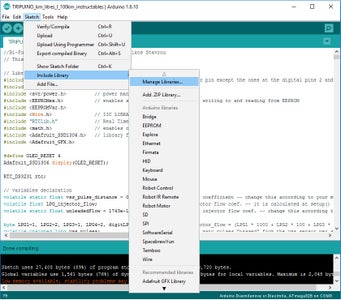
Instructions on how to install libraries into Arduino IDE see here.
You will need to make some modifications to the libraries. My preferred editor is the Notepad++.
Libraries:
- PinChangeInterrupt by NicoHood: This library enables the interrupts to the other pins except INT0 and INT1 (Digital Pins 2 and 3)
- Adafruit GFX Library by Adafruit
- Adafruit SSD1306 by Adafruit: library for the oled display
Modification #1: Once you install the Adafruit SSD1306 library go the library folder (usually: Documents\Arduino\Libraries ) and find the file: Adafruit_SSD1306.h. Open it using the Notepad++. Uncomment the line #define SSD1306_128_64 and comment the other two. This defines the size of our display.
Modification #2: At the same file. Find the line: #define SSD1306_I2C_ADDRESS 0x3C. If this address does not work for you, change the 0x3C with the address of your OLED display (usually there is one alternative - 0x3D). If this also does not work connect your OLED display to the Arduino as seen at the schematic and then you can find the address using i2c_scanner (by Frode Grimstad Bang) or this scanner (by Nick Gammon).
- EEPROMex library by Thijs Elenbaas: enables the reading from and writing to EEPROM with an easier way. We need this to store the values. The Bi-TripCo does not lose the measurement, if we disconnect the power supply.
Modification to EEPROMex: The library has a protection in case we make some mistake at our sketch and accidentally make continuous writes at the internal EEPROM, which will result to destroy the EEPROM (max ~100.000 writes). If you do not make any change to the code or you are sure what you have done then you must do the following in order to be able to take advantage of all the writing cycles.
Find the file EEPROMex.cpp and comment the line#define _EEPROMEX_DEBUG.
- RTClib by Adafruit: Real Time Clock module Library
Step 8: Schematic and Code Files...
- Here are the schematic diagram and the code files for both versions (metric and imperial/US).
- As you will notice, I tried to keep the code in the boundaries of the Arduino language. For that reason, I think that the code is quite simple and straightforward.
- Also, I am giving you a code file for the Leonardo to play around. If you connect the circuit that you see above, you will see that some readings (instant consumption and current speed) are not completely steady. This is happening because we read the values every second and the number of pulses that occur are not exactly the same every second. There is a way to smooth out these readings, if we take the average of the last 2 or 3 seconds. Nevertheless, if you see the total LPG litres, total Unleaded fuel and travelled distance you will notice that the measurements are absolutely right.
- Inside the code file for Leonardo, you can find which are the necessary modifications in order to use a second Arduino UNO instead.
As I mention in step 3 we need to do 7 external connections in total:
- LPG injector driving signal (see step 4)
- Petrol injector driving signal (see step 4)
- VSS signal (see step 5)
- Ignition signal (see step 4)
- 12V - battery voltage
- GND
- 1 connection for the thermistor (the other terminal of the thermistor goes to the chassis of the car = ground)
You have to be sure that you are making good connections. I wasted a lot of time on debugging problems which proved to be bad connections (eg. not working at all or freezing).
Before you upload the code, change the "Full_tank" variable to the capacity of your vehicle's LPG tank.


Step 9: Operating Instructions
As you will see, I gave more emphasis on readings related to the LPG, since this is the main fuel of a bi-fuel car. With some easy modifications in the code you can have the same readings for the petrol system, too.
Every time the ignition key is turned to ON, the Bi-TripCo wakes up, the logo screen appears for 2 seconds and the next screen is the screen that you saw before you turn the key to off.
The very first time that you 'll switch the ignition on, the first screen is the Instant LPG consumption.
At this screen press and hold button no 2 to go to "LPG Coef." setting menu where you can change the LPG coef. according to your measurements.
When you turn off the ignition key it stores the recorded values and enters the sleep mode.
Button no. 1:
Short press function only
- Changes the misc screens forward
- Changes Hour at the "Time Setting" menu
- Changes the value of the selected digit at the "LPG Coef." menu.
Button no. 2:
Short press (the changes are made on release):
- Changes the misc screens backwards
- Changes the Minutes at the "Time Setting" menu.
- Change the selected digit at the "LPG Coef." setting menu.
Long press (press and hold for 3 seconds):
- When you see the Time and temperature screen goes to "Time Set" menu.
- At the "Time Set" menu goes back to the screen, that shows Temperature and Time.
- Long press at the Instant LPG Consumption screen goes to "LPG Coef." menu.
- Long press at the "LPG Coef." menu stores the new value of the LPG coefficient and goes back to the Instant LPG Consumption.
- Long press at Average Speed, Distance travelled, LPG litres used and Unleaded Fuel Used resets the corresponding reading to zero.
- Long press at either Average LPG Consumption or Average Unleaded Consumption resets both of them.
- Long press at Remaining Fuel in tank resets the tank to the full capacity of the tank and remaining distance is reset with respect to the current average consumption.
The sequence of the screens is:
- Instant LPG consumption (l/100km or MPG -- when speed = 0 shows the instant consumption in l/h or Gal/h )
- Average LPG Consumption (l/100km or MPG)
- Instant Speed (km/h or mph)
- Average Speed (km/h or mph)
- Travelled Distance (km or miles)
- Remaining distanceto empty (km or miles - in conjunction with the average LPG consumption and the remaining LPG litres in tank)
- Total LPG Burnt (litres or gallons)
- Remaining LPG (litres or gallons)
- Outside Temperature and Clock (Celsius or Fahrenheit) -- when the temperature is below 3 degrees of Celsius (or 38 Fahrenheit) it shows a warning (a snowflake at the upper left corner of the display.
- Average Unleaded fuel consumption (l/100km or MPG)
- Total Unleaded Fuel burnt (Litres or Gallons)
Step 10: Calibration...


After you successfully install the Bi-TripCo to your car and seems to work, you have to calibrate it.
The first time that you turn the ignition key to on, the first screen will be the instant LPG consumption.
At this screen long press Button2 to set the LPG Coefficient.
A good value to start is:
a. For those who use l/100km set LPG Coef. = 1200
b. For those who use MPG version set it to around 3000
Initially, we care only for 3 readings:
- Travelled Distance
- Total LPG Burnt
- Total Unleaded Burnt
Any other reading will be completely false. Set the time if you haven't already done.
A. Determination of the vss_pulse_distance variable (distance related coefficient -- see the code)
If you want to make accurate calibration, you have to use a GPS or your phone's GPS with an app. The app that I used is GPS Essentials. Before you start to drive your car, open the app and go to settings:
- set GPS update interval and Tracking update interval to Fastest.
- Then go to units set your preferred unit system.
- Go back and select Dashboard. Tap to + and add the Distance covered. Reset the value by long press on it.
At the Bi-TripCo go to the Travelled Distance and reset it to zero.
Turn on the GPS (and GPS Essentials) and drive your car for some distance. Take care to have a good GPS signal. A good distance to drive is around 20km (The more you go, the more accurate your calibration will be - my test route at some time was around 88km). It is obvious that at that time the 2 readings (from GPS and Bi-TripCo) will not be equal. It's ok.
After your test route, write down the readings from the GPS and the Bi-TripCo.
We will use the Rule of Three to calculate the correct vss_pulse_distance variable.
Assuming that the readings are:
GPS: 10km
Bi-TripCo: 12km
and the vss_pulse_distance variable with which you make the test route is the one that is at the code files that I used: 0.0003816033
then we have new vss_pulse_distance = old_vss_pulse_distance * (GPS_distance/ Bi-TripCo_Distance)
so, for the above values will have: new vss_pulse_distance = 0.0003816033 * (10 / 12) =0.0003180028
Take the Bi-TripCo off, correct the variable in the code and upload the code again.
Go for a test and see if it is ok. Now the 2 readings must be close enough.
B. Determination of the LPG (and Unleaded) Coefficient (LPG_injector_flow and unleadedFlow variables)
The following are applicable for both LPG and Unleaded Fuel.
- Put the values, I mentioned above for the LPG Coef.
- Go to your preferred gas station.
- Fill up your tank to complete full.
- At Bi-TripCo reset the value: Total LPG Burnt (or Total Unleaded Fuel Burnt) -- reset the Tank to full if you want, too.
- Drive your car, as you usually do, probably for some days, until you consume enough amount of LPG (or Unleaded fuel)
- Go back to the same gas station, at the same pump and fill up your tank again.
- Compare the amount of LPG you fill up and the value that the Bi-TripCo recorded that you have burnt
- Then do the following calculations:
eg. LPG litres filled up = 45lt
LPG litres by Bi-TripCo = 65lt
Initial LPG Coef. = 1200
- Calculate the calibrated LPG Coef. with the following formula (Rule of Three again)
The calibrated LPG Coef. = Initial LPG Coef. * ( LPG litres filled up / LPG litres Bi-TripCo )
So in this case: LPG Coef. = 1200 * (45 / 65) = 0831
- Go to Bi-TripCo and set the new value.
*For the unleadedFlow variable you need to upload again the code with the new value.
Fill up your tank at the same fuel station again to test the new value.
Now your Bi-TripCo is calibrated. Of course you will make some more tests, after the initial calibration, for longer distance and period, in order to be sure that everything is ok.
Step 11: Bi-TripCo on My Car - an Installation Idea


Here you will see pictures from the installation on my car (Honda Civic MB1 1.6iLS - an old, but reliable car) and mostly pictures from the modification I made to the original clock assembly, in order to place the OLED display in it.
That gave me also the ability to use the 2 pre-existed buttons, for the Bi-TripCo. I implemented the debouncing circuit inside the clock assembly (see the pictures).
The disadvantage of this is that I needed more external connections from the display to the "central unit" of the Bi-TripCo and that's why I had to deal with many connections problems. I wasn't too careful.
The cables, I used, are cat5 ethernet cables, for no specific reason. For that, I used RJ45 PCB connectors, which gives me the ability to take it off easily, in order to do some modifications or for development purposes.
I also used the case of an old ADSL modem to put it in, and I place it in the glove compartment.
The RTC does not fit inside, that's why it is outside of the case.
Also I used the MCP1702-5002 LDO Low Quiecent Current Regulator.
There is also a picture with the Honda logo that I used at first.
Finally
At the PCB pictures you can see some other components too and also some modifications that I have made (don't worry the schematic that I gave you is the right one). The extra components (you can see clearly a big transistor) it is used for the locking and unlocking of the doors. This extra circuit gives the ability to lock and unlock the car while the alarm is arming or disarming respectively. Also there is the ability to lock the car when the speed exceeds 10km/h and unlock when I turn the ignition key to OFF.
So, the number of the external connections in my case from 6 became 14!!! (mainly because the display and the buttons are not in the case with the main circuit) and the ethernet and RJ45 connectors was a good solution.
Thank you very much for your attention!!!

Second Prize in the
Microcontroller Contest 2017


