

Introduction: How to Build a Robotic Hand With Haptic Feedback

More by the author:


About: I enjoy working on all sorts of projects. Whether it is creating something with my forge or building the biggest thing I can think of in Minecraft, I am always trying to find new and interesting projects to wo…
For science fair this year, I felt like building something instead of doing an experiment. All I needed to do was look around Instructables for a project idea. I was inspired by njkl44's robotic hand since it reminds me so much of stuff out of science fiction movies. My goal was to create a system of haptic feedback from a robotic hand like that. The system provides a way for the person controlling the hand to "feel" what the robotic hand is feeling. I thought that this was an excellent project since it gave me something to do for science fair, and it provided me with a platform for constant development. In other words, I will not stop working on it. I will always try to come back to it, so I can make various improvements or redesign it every now and then.
njkl44's robotic hand:
https://www.instructables.com/id/Arduino-Wireless-Animatronic-Hand/
njkl44's robotic hand:
https://www.instructables.com/id/Arduino-Wireless-Animatronic-Hand/
Step 1: Materials and Tools


Materials:
Per Finger:
A2-70 bolts- 3 with a beveled head and 4 with a regular head for each finger
Nylon-insert lock nuts for the bolts
4-40 x 1/2" machine screw and matching nut
2-56 Threaded ball link (for connecting the finger to the servo)
Jumbo paperclip (used for connecting the ball links)
(x28) #4S washers
Electronics:
Arduino Mega
(x4) FSR
(x4) 4.5" Flexible Resistor
(x4) Mini Vibrating Motors
(x10) PCB Screw Terminals
(x4) 22k Resistors
(x4) 10k Resistors
24AWG wire in a twisted pair (the pairs make it easier to manage the wires)
(x4) Hobby Servos
Misc. breadboarding equipment
6V Power Source (I used a 4xAA battery holder)
Other:
5mm Acrylic
Duct Tape
Golve
Heat-Shrink Tubing
Thread
Tools:
Laser Cutter
Dremel
Drill Press
Hot Glue Gun
Soldering Iron
Safety Glasses
Needle
Step 2: The Design

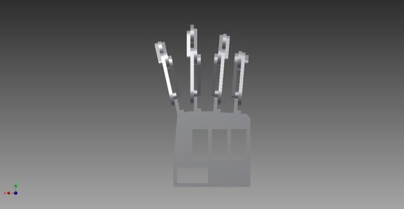


Each of the fingers uses two sets of four-bar linkage. I will show you how this works with the two pictures of the finger below.
For the parts, I was able to get them laser cut out of acrylic at my local hackerspace, HeatSync Labs. Acrylic is an excellent material for smaller loads and basic testing, but if there is any sort of major strain on the finger, you run the risk of snapping the parts. Instead of acrylic, it would be better to get the parts made out of metal for larger loads.
There is no scale on the .dxf files. For the fingers, the holes should be 2.8mm. For the palm, the rectangles are 20x40mm. I used Hitec HS-322 HD servos, and they fit perfectly. You will have to take the servo case off and put it back together in the hand since there is a small lip where the wires come out.
Attachments

Step 3: Put the Fingers Together


Originally, the fingers used 4-40 bolts for all of the holes, but since the metric bolts fit better, I swapped all of the bolts out.
I needed to bevel the inside holes on the parts in order for the beveled bolts to sit flush with the surface of the acrylic. To do this, I used a drill press with a drill bit the same size as the beveled heads. I also cut the bolts down a bit to prevent them from catching between the fingers.
CUT THE BOLTS CAREFULLY. This can cause trouble if done without safety glasses and gloves. Also remember to put on the regular nuts before cutting the bolts and take them off afterwards. This will keep the threading from deforming when you put the lock nuts on.
For putting the finger together:
Put the beveled bolts on first.
Then the other bolts in any order.
Each bolt also gets its own washer and lock nut
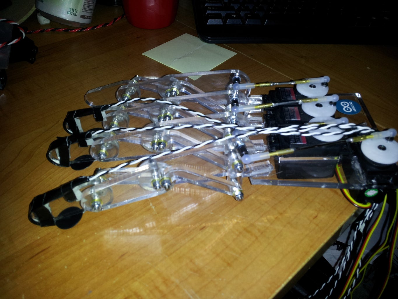
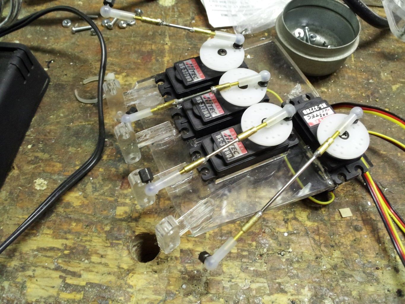
Step 4: Assemble the Robotic Hand


For attaching the fingers, rough up the acrylic that will be glued. This provides the hot glue with something that it can grab on to. Also, position the fingers at angles similar to the human hand. Adjust them so the bolts do not interfere between the fingers,
For each FSR, solder the twisted wires on. I used about 2 feet of wire for each FSR. Wrap the FSR in duct tape, like in the picture below. This will allow them to be taped to the robotic hand. Make sure there is some tape holding down a small portion of the wires. If this is not done, the FSR might bend too much just above soldering joint and break.
For the servos, you need to take apart the case and put it back together on the hand. They cannot slide in due to the lip where the wires come out. Put a bit of hot glue between the servo case and the acrylic. This will keep them in place.
Cut the jumbo paperclips to the right size and solder them on the the ball links. The nice thing about the ball links is that they can be adjusted afterwards by screwing the links on a bit more or a bit less.
The single 4-40 bolt goes on the top of the first segment of the finger and attaches to the ball link.
Step 5: Assemble Your Hand

Sew all of the parts onto an old glove. Make sure it matches the robotic hand (left glove for left robotic hand and right glove for right robotic hand). The side it is can be altered by swapping some of the wires around.
Solder the twisted wire to the motors and to the flex resistors. Again, I used about 2 feet of wire, but how much you use depends on how far away from the Arduino you want to get.
In my original hand, I used the twisted pairs out of an Ethernet cable. The color coding made wire management simpler, but the wires were a bit stiff. The stiffness does not affect the functionality of the hand, but it does make the glove feel a bit weird to wear. This can be fixed by using stranded wire instead of solid core wire.
Step 6: The Electronics


Each of the sensors uses a voltage divider. The FSRs get a 10k resistor, and the flex resistors get a 22k resistor. The voltage divider works with the changing resistance of the sensors. When the resistance is higher for the variable resistor, there is a larger voltage drop across the variable resistor. The voltage dividers are supplied with +5V, and that drop in 5V is split between the two resistors. The Arduino measures the voltage between the resistors and returns value between 0 and 1023 based on the voltage reading (0 being 0V and 1023 being 5V).
Step 7: Program the Hand
I have attached the code from my first version. That time, I used two regular Arduinos since I needed 8 Analog In pins. It also isolated the two processes going on: positioning the fingers and measuring the pressures. For my second version (this version) I used an Arduino Mega, so I could fit all of the inputs on one board. As for the code, I pretty much copied and pasted the servo positioning into the pressure reading loop and changed the pin labels around.
**Important**
For the servo positioning, there still needs to be some work done on limiting the rotation. If they rotate too far, something may break. This is how I broke the finger.
As I said in the intro, I will always come back to this project to try to improve it bit by bit. Since this is one of my first Arduino programs, there are most likely some inefficiencies in the code. Feel free to post potential modifications.
Step 8: Hook Everything Up
This is one of the more challenging parts. Make sure to check and double check all of the connections.
Each sensor gets its own terminal. One wire goes in one slot, and the other wire goes in the other slot. Since the sensors are resistors, the direction they go in does not matter.
Going from left to right on the terminals:
(each resistor with its own terminal)
Flex resistors(glove)- index finger
middle finger
ring finger
pinky
(each of the four wires goes in its own slot)
Motor grounds- Order does not matter; just remember that the positive wires hook directly into the Arduino
FSRs(robotic hand)- index finger
middle finger
ring finger
pinky
The servos are hooked up on the other side of the breadboard.
Servo pins:
Red- positive power source
Black- ground
White/Yellow- signal (the Digital Out pin the servo is attached to on the Arduino)
All of the jumper wires go from the board to the appropriate pins on the Arduino. (flex sensor 1 to Analog In 0, flex sensor 2 to Analog In 2, etc.)
Step 9: Enjoy!

Have fun with this project, and feel free to ask any questions!
-zach
-zach
