

Introduction: How to Make a Voltage-Controlled Oscillator


The objective of this Instructable is to show you one method of turning DC values, such as those from a thermometer, pH sensor, or pressure sensor into a frequency which can be used to send information over the microphone band of an audio jack to a smartphone.
We assumed an input DC voltage as our sensor and built a voltage-controlled oscillator (VCO) to turn different DC voltages into correspondingly different frequencies, which the microphone input into the smart phone’s audio port reads as different tones.
Step 1: What You Need

Tools
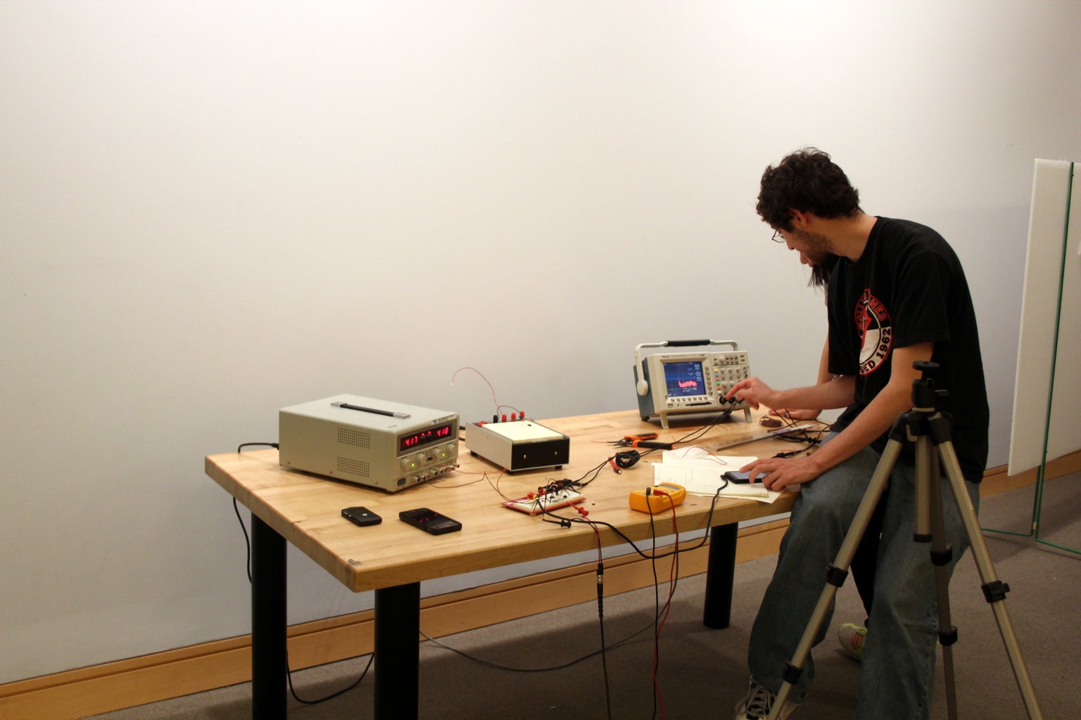
Oscilloscope & lead wires
Frequency generator
Device that plays audio and takes microphone over a 3.5mm audio jack (we are using a Samsung Galaxy Vibrant).
Breadboard
Parts
3.5mm TRRS Audio cable
Resistors (two 100kΩ and one 100Ω)
1μF Capacitor
OPA 551 [http://www.ti.com/lit/ds/symlink/opa552.pdf] (1)
10Ω-10kΩ Potentiometer
Assumed Knowledge
You can use a breadboard. If you’ve never used one before, see https://www.instructables.com/id/Breadboard-How-To/.
You can use an oscilloscope. If you’ve never used one before, see https://www.instructables.com/id/Oscilloscope-How-To/.
Step 2: Build an Oscillator
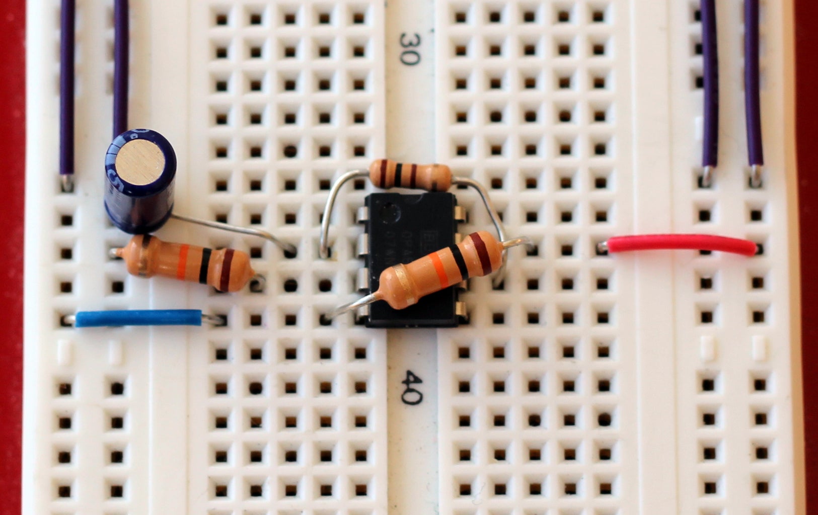


Why: There are many designs of VCO, but we chose a hysteretic oscillator, which is a type of relaxation oscillator. If you're interested in oscillator design, this website has good information.
Theory: The comparator (an op-amp, in our case) generates a positive feedback loop between the positive and negative voltages. This feedback charges the capacitor when it draws from the positive voltage, then once the capacitor fills, it discharges, switching the power draw from positive to negative. This process repeats to oscillate continuously.
The frequency of the oscillation is thus dependent upon the size of the capacitor and on the input voltages.
Practice: Values should be selected so that the frequency output will be in the audio range, approximately 16 Hz to 20 kHz.
Power the op amp according to the values on its data sheet.
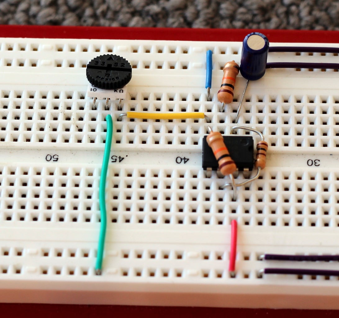
Step 3: Control Voltage: Install a Potentiometer


Step 4: Control Voltage: Frequency Generator

Step 5: Tips for Swapping in a Sensor Circuit

Why: If you are using this circuit to gain real information, not just play around with a potentiometer, you will want to swap in a real voltage-changing circuit and read its frequency values.
Theory: We are currently modulating voltage with a potentiometer. If the frequency is altered based on this change in DC voltage, a change in DC voltage from a different source should also modulate the frequency.
Practice: You want the voltage from your sensing circuit to match the voltage range you identified by sweeping voltages above. If your sensing circuit voltages are higher or lower than that range, you will see clipping. If the range of your sensing circuit voltage output is very small, your readings will have low resolution.
Plug in your sensing circuit output in place of the potentiometer. Different output frequencies of your VCO will correspond to different voltages inputted by your sensor. All’s left is decoding by measuring the frequency of these new AC voltages on your phone. Congratulations, you can now send information to your phone over an audio jack!
Step 6: Bonus: Pranking!


Participated in the
Epilog Challenge V


