

Introduction: How to Teach the Language of 3D Modeling and Design


Words are just labels, right? Well, sort of.
Words can stir your emotions or make you giggle; however, they can also open doors for your students into career fields they never dreamed of - like architecture, animation, or engineering, to name a few.
Traditional instruction often only scratches the surface of meaning, not just in math, but in other subjects too. Just like "design" can be a verb, a noun, or even an adjective, many of the math concepts you teach are also layered in meaning. They can be learned, but, more importantly, they can also be DONE - and can even be innovated upon by your students. 3D design is a powerful tool for facilitating this kind of hands-on, deep learning.
By introducing 3D design to your students, you are not only teaching them a highly in-demand skill, but also a whole new professional language.
Sounds daunting, huh? Please don't fret. Instead, let this Instructable be your guide!
Through this Instructable, you will walk away with:
- Definitions and examples of 3D design terminology students will find useful in getting started in both Tinkercad and Fusion 360
- New ways of teaching familiar math concepts through 3D design in order to uncover deeper meaning
- Strategies for connecting math with the arts
So let’s set sail into a whole new dimension of vocabulary to teach your students!
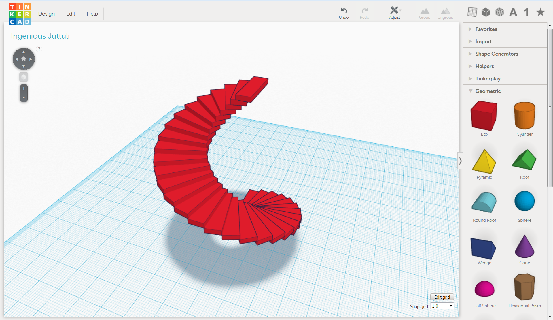
Step 1: Vocabulary Basics in 3D Modeling

In launching into 3D design for the first time, it makes sense to pare the language down to what's most essential and high-leverage. Below are some words to get your students talking. Note: We have also included references to commands and features in Tinkercad in order to provide some additional context for the terms; however most of these words are applicable to other computer programs in addition to some of the math concepts you might already teach.
Align: to place or arrange (things) in a straight line. To use the Align tool, select at least two objects by Shift left-clicking on them or by dragging a box around them. Once selected, click on the Align icon at the top. Simply move your mouse over a node (the black dots) to preview the move.
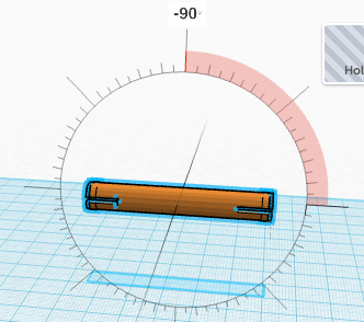
Angle: a figure formed by two rays, called the sides of the angle, sharing a common endpoint, called the vertex of the angle. It also measures the amount of turn an object is rotating, for example: 45 degrees or 90 degrees (also called a "right angle.")
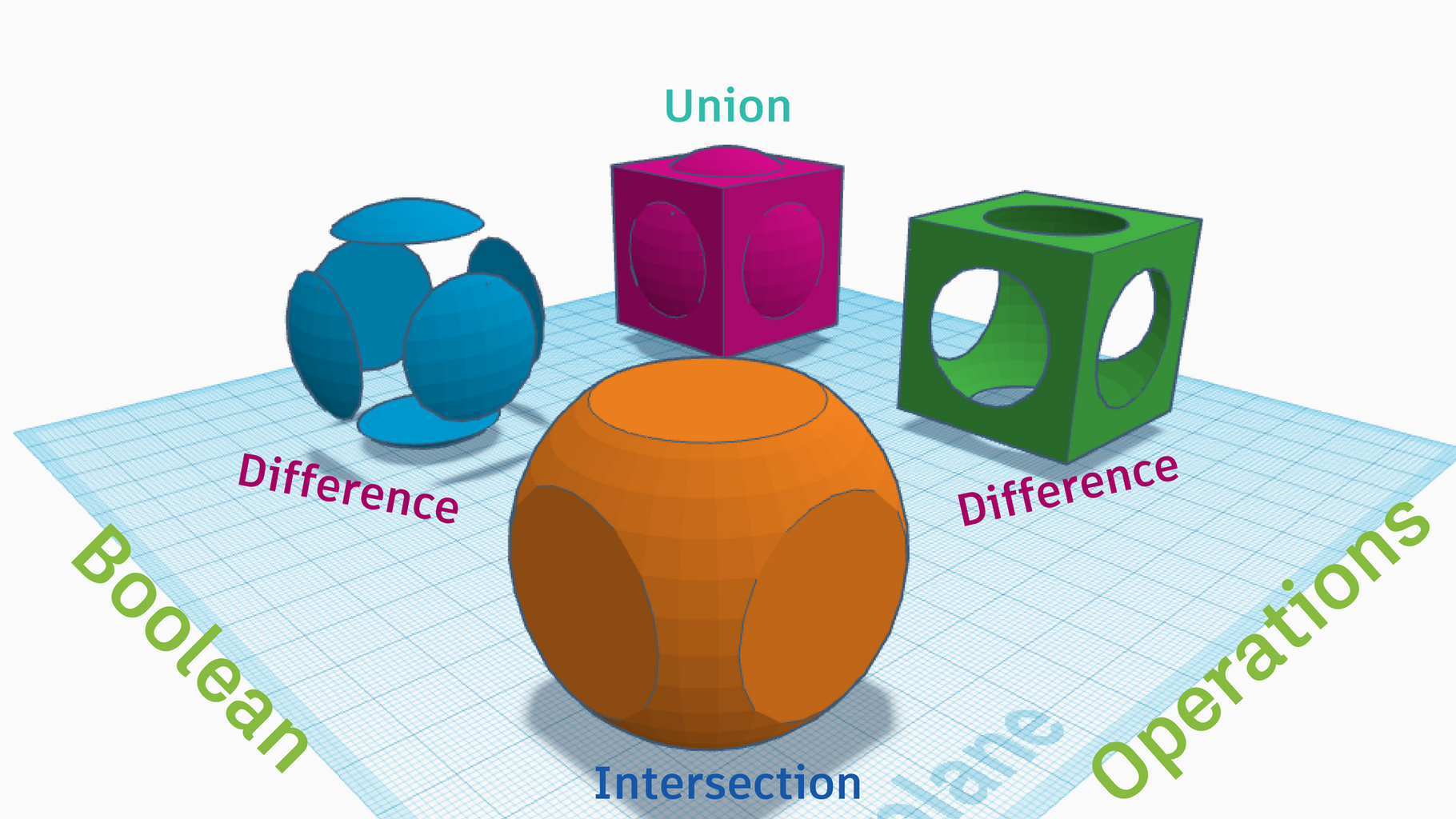
Boolean operation: in 3D design, the action of adding, subtracting, or combining primitive shapes.
CAD: computer-aided design is the use of computer systems to aid in the creation, modification, analysis, or optimization of a design. CAD software is used to increase the productivity of the designer and to assist in the fabrication process. Using CAD is often faster than drafting by hand, and it also allows you to easily export files, such as for 3D printing.
Diameter: a straight line going through the center of a circle connecting two points on the circumference.
Dimensions: a measurable extent of some kind, such as length, width, or height. In its simplest form: a line describes one dimension, a plane describes two dimensions, and a cube describes three dimensions.
Duplicate: to make or be an exact copy of. To duplicate an object, use Ctrl + D and then drag it out or use the arrow keys.
Export: to convert a file into another format than the one it is currently in. For example, you must export your design in order to print it. Tinkercad also allows you to "share" your design in the form of a PNG image file.
Fabricate: to construct or manufacture. To "make" your design. You can make almost anything through 3D printing or laser cutting.
Flip: a tool that allows you to create the mirror image of an object or to flip it along the x, y, or z axis. Use the Flip icon after you have selected the object. Use Flip and Duplicate together to create complex designs more efficiently.
Gallery: a collection of creations grouped together. Creations in the Tinkercad gallery typically can be copied and tinkered for analysis, modification, and inspiration. You can publish your design by changing the setting to public when you are ready for an audience.
Group: to combine two or more shapes into a part. Do this by selecting them and then choosing the Group icon at the top.
Handle: the little squares that appear on the shape when you select it that allow you to resize it by pulling and pushing them.
Hole: a tool used to subtract from a solid shape.
Import: to bring a file from a different program into the one you're using. In Tinkercad, you can import STL files in order to analyze and build upon the 3D designs of others, or SVG files in order to add 2D images like logos and patterns to your designs.
Millimeter: a millimeter is 1/32 or 0.039 of an inch. This is the default unit of measurement in Tinkercad.
Pan: to rotate a camera on the horizontal or vertical axis. Use the right mouse button to do this.
Part: one or more shapes that have been grouped together.
Perpendicular: at an angle of 90 degrees to a given line, plane, or surface.
Plane: a flat surface with no thickness.
Primitive (or shape): a starting point or building block for 3D design. These shapes can be added, subtracted, and combined with one another to build just about anything. They include: Cube (Box), Cylinder, Tube, Sphere, Torus, and Cone.
Rotate: to move in a circle around an axis or center. When you select an object, the arrows are for rotation. You can rotate on any of the planes.
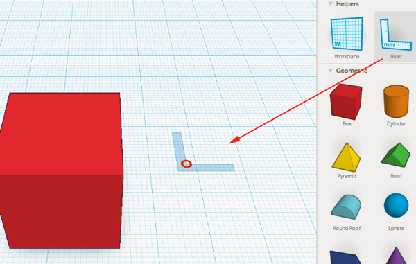
Ruler: you know what this is in real life! You can access this handy tool for measuring by dragging it out on the workplane. This can enhance your design by allowing you to see an object's exact location on the workplane, and also by making it easier to manually set measurements.
Scale: to change the size of an object so that its dimensions are proportional to the original size. You can do this by holding down the Shift key while pushing and pulling the handles to resize.
Shortcut: computer keys that help provide an easier and usually quicker method of navigating and executing commands in computer software programs. Here is a link to the Tinkercad shortcut keys.
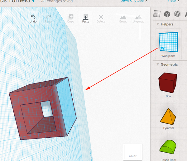
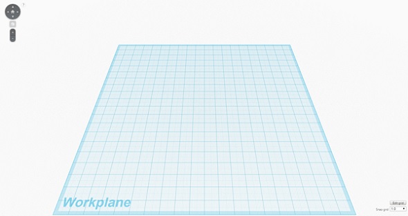
Workplane: the large, blue grid where you create your designs. You can drag out new workplanes onto the surfaces of your shapes for easier stacking and more precise measuring.
X, Y, Z axes: an axis is an imaginary line about which an object can rotate, which also serves as a fixed reference for measuring position. In a Cartesian coordinate system, the z-axis is perpendicular to both the x-axis and y-axis and usually represents depth or the third dimension. You can lift objects up off the workplane and along the z axis by using the black arrow pointing up from the center of the object.
Zoom: to move a camera from a long shot to a close-up gradually. Use the wheel on the mouse to do this.
For more information about how to bring Tinkercad into your classroom, read this Instructable.
To download a PDF version of this 3D Design Glossary for Beginners, click the button below.
Attachments

Step 2: Advance Your 3D Design Lingo - Intermediate Vocabulary


Look at you, stacking and aligning like a pro! Ready to up your game?
After your students master the basic terminology and design skills, challenge them with some advanced vocab to carry them into this next dimension:
Bevel: See "Chamfer." Or to get technical, read this.
Chamfer: a symmetrical sloping surface at an edge or corner of a shape, usually cut at a 45 degree angle. You could accomplish this by using the Hole tool and rotating it to subtract from a solid shape.
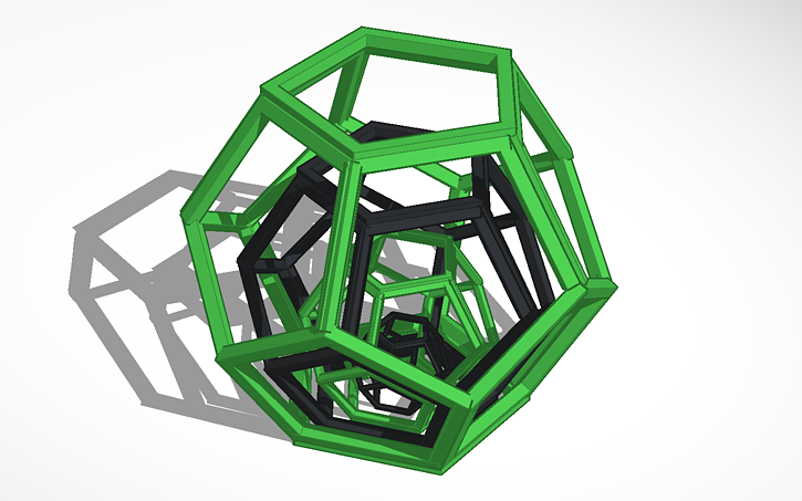
Concentric: circles or shapes which share the same center.
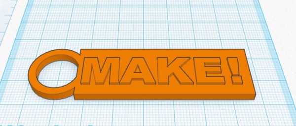
Emboss: to carve, mold, or stamp a design onto a surface so that it stands out in relief. One way to do this is by importing an SVG file and placing it onto the surface of a shape or part, aligning it to your specifications, and then grouping it all together.
Deboss: to stamp a design into the surface of an object so that it is indented. One way to do this is by importing an SVG file and placing it onto the surface of a shape or part, sinking it and aligning it to your specifications, turning the SVG shape into a hole, and then grouping it all together.
Extrude: to extend a 2D image into a 3D object in a straight line.
Fillet: to make a rounded edge. Here is a cool tool for achieving this effect.
File formats: You can export and import a variety of file types in Tinkercad. Here are what they do and what they are used for -
OBJ: this file type is capable of representing a greater degree of texture and color and, as a result, is more commonly used for animation or with high-end printers that can control color. OBJ also supports multiple parts/shapes in a single file where an STL doesn't. OBJ also works where most STL files do, but generally is only used when specifically required.
PNG: a type of graphics file similar to a JPG that Tinkercad uses for sharing still images of your designs.
STL: one of the most commonly used file formats for 3D printing. It is due to the fact that most CAD software has the feature of exporting models in STL format, and most 3D printers support it. The file generates the surface geometry of the modeled object only. STL stands for stereolithography.
SVG: stands for scalable vector graphics. The big difference between "rasterized bitmap images," like PNGs and JPGs, and vector images is that vector images are composed of a fixed set of shapes, whereas the others are made up of a fixed set of pixels. As a result, scaling the rasterized bitmap reveals the pixels, while scaling the vector image preserves the shapes. SVGs are commonly used for any type of image that might require a great deal of flexibility in size (think company logos that must be tiny for business cards but also blown up huge for billboards.) SVG is also the standard file format for laser cutting.
JavaScript: a scripting language for computers that is used for making shapes in Tinkercad. It is often run in web browser applications to create dynamic content like a popup message or a live clock. It is not related to the programming language Java.
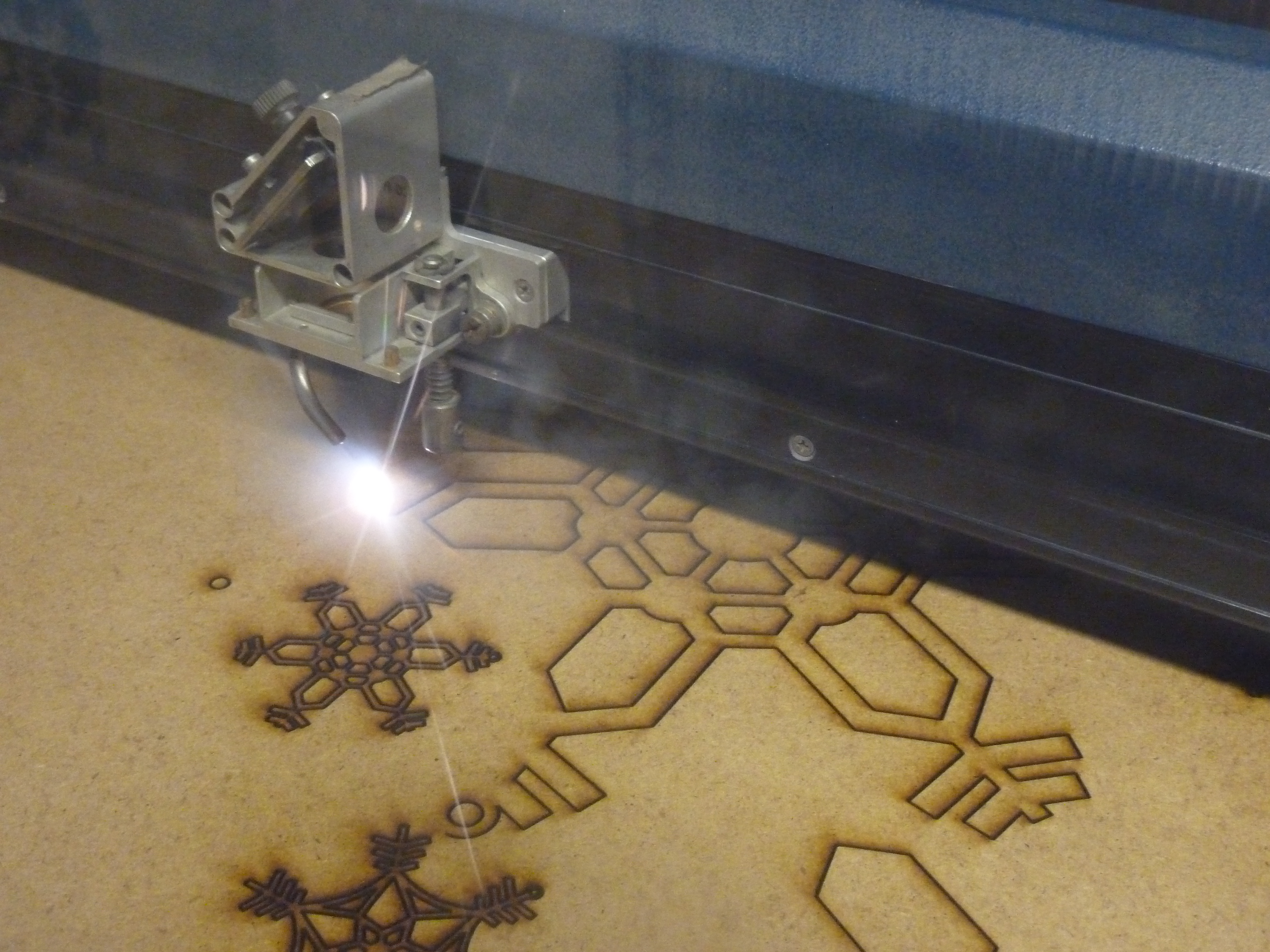
Laser cutting: a technology that uses a laser to cut materials using great precision.
Offset: to move out of alignment.
Orthographic view: two-dimensional view of a three-dimensional object. Orthographic views represent the exact shape of an object as seen from one side at a time as you are looking perpendicularly at it. Depth is not shown. In Tinkercad, you can switch to orthographic view by clicking on the icon that looks like a block at the bottom of the navigation controls. This is useful when you are centering, stacking, or zooming out to analyze your design.
Perspective view: a view of a three-dimensional image that portrays height, width, and depth for a more realistic image or graphic. In Tinkercad, you can toggle between perspective and orthographic views by clicking on the icon that looks like a block at the bottom of the navigation controls.
Shape generator: some of Tinkercad's shapes are created by our community of developers who use JavaScript to program them. If you want to learn how any of the Shape Generators were made, you can click on View Code (as long as the author has allowed others to view it), and this will take you to the Editor. This is also where you can create your own Shape Generator. Many of the featured shapes offer a greater degree of flexibility in editing - including handles that allow for the creation of more organic curves. Read more about this here.
Smart duplicate: To duplicate an object in Tinkercad, use Ctrl + D. To take it a step further, “Smart duplicate” is like a short-term memory that knows what you just did, and will repeat it to create patterns and repetition while copying objects. Remembering all those steps, this feature will allow you to create complex repeating patterns in seconds.
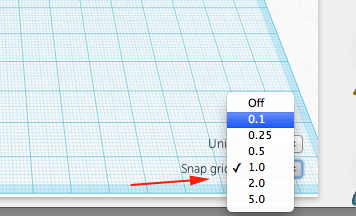
Snap grid: a setting in the lower right of the canvas that allows you to adjust the precision of your commands. For example, you can change the snap to 5 millimeters in order to move a shape more quickly across the workplane, or you could change it to .1 millimeter in order pull out the size of a shape in smaller increments. You can also edit the grid to change the unit of measurement to inches or to resize the dimensions of the grid for compatibility with different 3D printers.
Symmetry: the quality of being made up of exactly similar parts facing each other or around an axis. Symmetry is an important concept for 3D design because it allows you to enhance the complexity of what you are making more efficiently by designing half of a part and then flipping, duplicating, and grouping the two resulting parts into one.
Tangent: a line or plane touching, but not intersecting, a curve or curved surface.
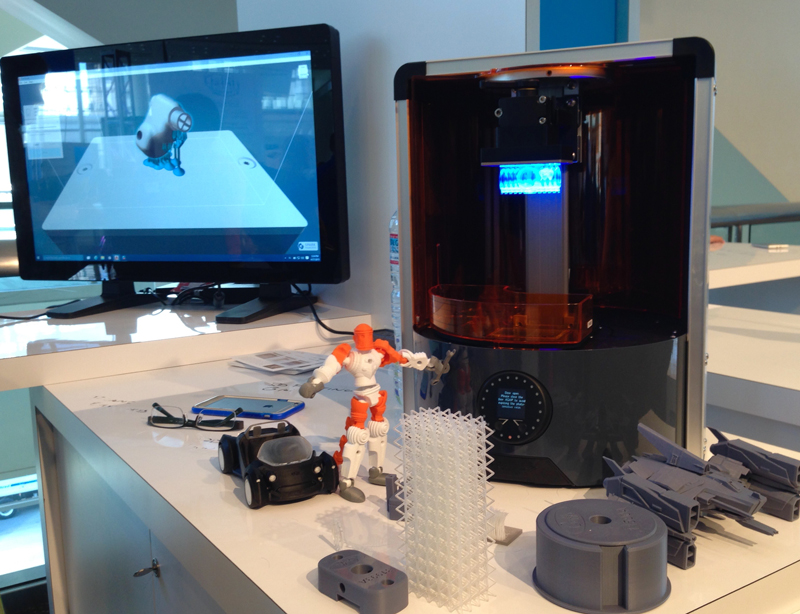
3D printing: 3D printing or additive manufacturing is a process of making three-dimensional solid objects from a digital file. In an additive process, an object is created by laying down successive layers of material until the object is finished. This process can use a wide variety of materials, but the most common is plastic.
Ready to fabricate your design? Here is a great glossary of words to better understand the 3D printing process.
To download a PDF version of this Intermediate 3D Design Glossary, click the button below.
Attachments
Step 3: Talk Like a Pro - Going Advanced

Waiting to take a step into the next level? What's stopping you? Go for it!
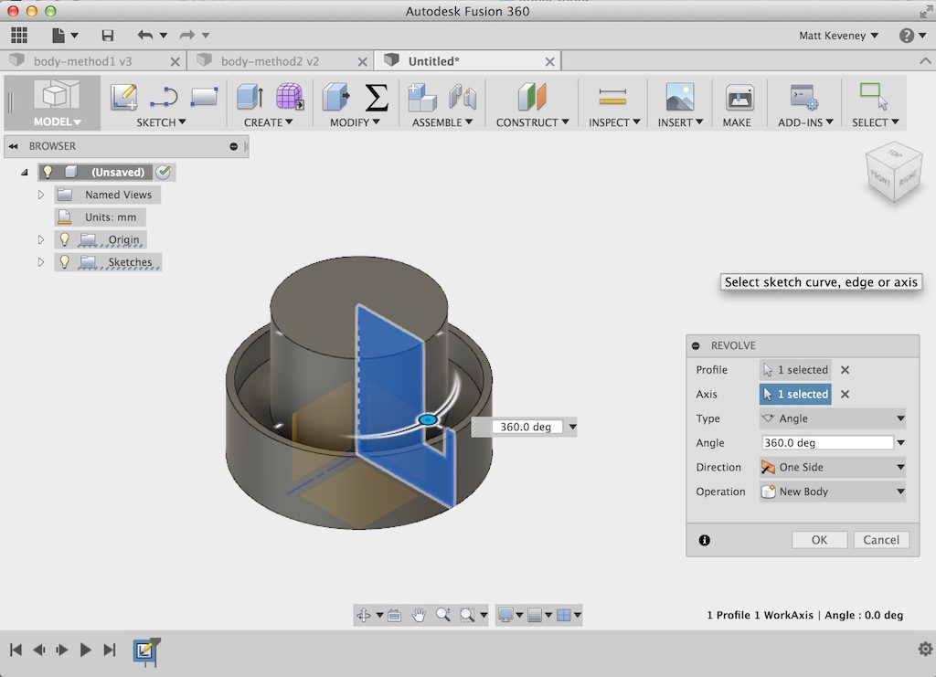
Maybe your students have mastered Tinkercad and are ready for a bigger challenge and advanced features. Don't worry, we've got you covered. The next step in advancing design skills is learning all the awesome power behind Fusion 360. Before you begin, you should sign up for a Fusion 360 account (free for educators and students!) and check out the system requirements here.
In exploring the new world of Fusion 360 you will also find there is much familiar with Tinkercad. This is because both products are continuing to be built out in ways that align with one another and forge a clear and accessible path for all users into more advanced creating.
These words are some fuel for your journey:
Body: a modeling tool. You can use separate bodies to add or remove geometry to achieve the final shape of your design. For example, you may create a coffee mug by making a body for the cup and another body for the handle, and then join them together. Bodies can be compared to shapes in Tinkercad - for example: where shapes can be grouped together into parts, bodies can be combined into components. Fusion 360 supports three types of bodies: solid/surface bodies, sculpt bodies, and mesh bodies.
Combine: to unite two bodies or components into a single component. Combining can be compared to grouping in Tinkercad.
Components: "containers" for other modeling entities, which can include sketches, construction geometry, bodies, and even other components. Components represent real-world parts; something that is manufactured and that may be assembled to one another. If you already have a plan for what you are making, it is best to begin your design with a component and then construct the bodies within it.
Cross section: to cut an object off at right angles to an axis. In Fusion 360, you might do this to analyze your design.
Freeform: See "Sculpt."
Joint: used to assemble components and create mechanical relationships between components, including defining movement. Learn more about different types of joints here.
Loft: Transitioning from one shape to a different shape over a specified distance. For example: from a rectangle to a circle or like the hull of a ship.
Mesh: is a collection of vertices, edges, and faces that can describe the shape of a 3D object. A vertex is a single point. An edge is a straight line segment connecting two vertices. A face is a flat surface enclosed by edges. While Fusion 360 creates solid/surface bodies, it supports the modeling of mesh bodies also.
Parametric modeling: a tool that lets you describe what you want to make numerically and allows designers to change an entire object by changing only one of its attributes through assigning constraints - or parameters. For example, a parameter could describe an endcap on a pipe. When you create the model, the endcap is automatically placed at the end of the pipe, no matter what changes you make to the pipe’s length.
Path: a line that appears when you sketch in Fusion 360. A path is made up of a series of points called “anchor points” and line segments between these points. The anchor points on the either end of a path have “control handles” and these can be used to control the direction of the curved path.
Profile: a 2D sketch that can be extruded to make a 3D object.
Render: to create a final image of a model that shows all of the surface properties that have been applied to an object. This process involves adding all colors, shading, and other elements, such as the physical appearance of materials, that add realism.
Revolve: to sweep a 2D object around an axis, resulting in a three-dimensional shape.
Sculpt: a modeling approach that creates organically shaped models using direct manipulation. You can start with one of five basic Freeform shapes to do this: Box, Quadball, Cylinder, Torus, and Sphere. In the Sculpt Workspace, you can rapidly explore forms by simply pressing and pulling on subdivided surfaces.
Shell: to remove material from a part interior, creating a hollow cavity with walls of a specified thickness.
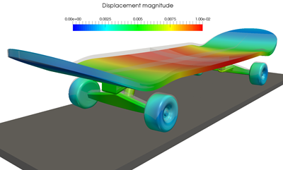
Simulate: to examine and test a design through a computer-aided imitation of how it might function in the real world. These quick iterations or tests are meant to provide useful visual feedback in order to better understand and improve a design before it is actually fabricated.
Slice: to divide a solid object into two or more separate 3D objects.
Sweep: to extend a profile along a curvy line into a 3D object. It requires two sketches - one for the profile and one for the path.
To download a PDF version of this Advanced 3D Design Glossary, click the button below.
Attachments
Step 4: Teach the Math Behind the Language


By now, you are probably already seeing shapes everywhere! There's actually a word for that too... (See Tetris Effect.)
But, seriously, introducing 3D design to your students opens a portal into teaching math in a new way that emphasizes conceptual understanding and has the capacity to reach students who require additional context and representation when learning math. It also sets the stage for students to begin to speak like real mathematicians AND designers. Here's how:
Bring Geometry to a deeper level.
From teaching the names of primitives to the math behind the creation of shapes, there is so much to explore.
Some related words to think about: Union, Intersection, and Differences (or Subtraction) can all be taught within the context of using basic Boolean operations in Tinkercad.
Send your students on a mission through virtual 3D space.
Basic 3D concepts dovetail nicely with teaching about Cartesian space.
Some more words to ponder: Origin, Coordinates, and Positive and Negative can all be taught as students are also learning how to navigate the workplane. To travel a step further: This also can connect to animation!
Take your lesson to infinity and beyond!
Want to unlock to a secret to making math enjoyable to even your biggest math critic? Teach your students about Smart duplicate. If you select an object, press Ctrl + D and move, rotate and/or scale it and then press Ctrl + D multiple times afterwards, it will continue creating new duplicates with the same interval from the last one made as between the original and the first duplicate.
Then sneak in some new vocabulary: Similarity, Congruence, Patterns, Tessellation, and Parallel.
Teach at the intersection of Math and Art.
Several of the featured shape generators in Tinkercad illustrate a technique for creating curves that was attributed to and named after a French engineer, Pierre Bézier, who used them for the body design of Renault's cars in the 1970s. In addition to this, there are many ways to use 3D design to teach math, art, and language at the same time.
Consider how you might apply these words to a 3D design lesson: Bezier Curve, Spline, Fractals, and Voronoi Diagram.
Bonus: Here's a video that shows how to make a tea light in Tinkercad using the Voronoi Tile shape generator - or better yet teach your students how to draw their own patterns by hand and then show them how to convert sketches to SVGs and import them into Tinkercad.
Step 5: Learn, Network and Be Inspired

Now that you are up to speed with the language of 3D design, you can pass on the knowledge to your students through this Instructable or via the document at the end of this step that lists all of these terms - grouped by Beginner, Intermediate, and Advanced - in a handy PDF format.
Just like learning a foreign language, the best way for your students to gain fluency in the language of 3D design is for them to immerse themselves in a community that speaks it.
When you think about inspiring innovators like Zaha Hadid or Guillermo del Toro, it is easy to forget that they were both kids once. Teachers like you - impacting the next generation in so many ways - are helping shape our future thought leaders and makers who will, in turn, shape our society for the better. So thank you for providing your students with access to language and learning opportunities so they can become anything!
Please let us know how we did with this list of words in the comments below. Are we missing anything? What other ways are you teaching your students to acquire the professional language they need to succeed? What is your greatest challenge in doing this? Let's discuss!


