

Introduction: How to Use a Breadboard (with Example)


A Solderless Breadboard also known as a Protoboard is a prototyping space(board) that every electronics enthusiasts must have. A breadboard let's you test circuits or try out new ones without the hassle of soldering. Watch the video above or continue reading for in depth description.
Link to the YouTube Video HERE.
Step 1: What's Inside It?


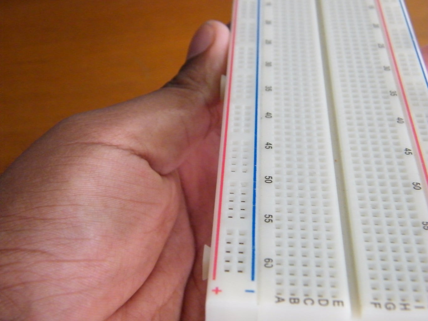
Breadboards come in different sizes and colours but on the inside they are all the same. They all have an array of conductive strips that connect the points together.
There are two parts of each breadboard:
- There are the two sets of power rails on both sides of the breadboard usually marked by red(positive) and blue(ground) which are connected all along the breadboard.
- In the middle is your main prototyping space made up of sets of five rows marked by alphabets A-E and F-J. These are connected vertically i.e. in the first column A,B,C,D and E are connected together and F,J,H,I and J are connected together separated by the middle grove.
That gap in the middle is just the right size to accommodate IC's(Integrated Circuits) in the dip form factor. When an IC is placed across that gap then none of its legs or pins are connected together (which is how it should be, if you have any doubt).
Let's make a simple circuit in the next step.
Step 2: Materials Required


Materials required:
- Breadboard
- Wires
- A LED
- A 100 ohm resistor(brown black black black brown)
- A battery or another power source
Buy the parts :
- Breadboard : http://goo.gl/yxUlDw
- Jumper Wires : http://goo.gl/zdFmqt
- LED's : http://goo.gl/XKfA9Q
- Resistors : http://goo.gl/rPP8VB
- Breadboard Power Supply : http://goo.gl/IwQX4g (If you want to get fancy with the power)
Step 3: The CIrcuit

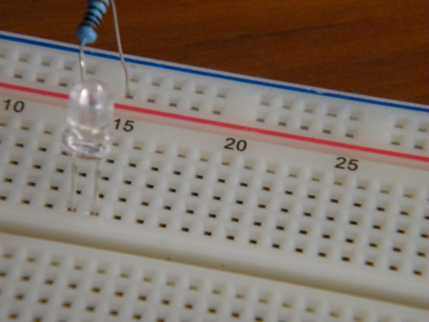


- Put one end of the resistor in the positive power rail(red) and the other end in one of the rows
- Put the positive end of the LED (usually the longer lead) in the same row as the resistor and the negative lead in a adjacent row(not the same row). This way the resistor is connected to the anode(+ve) of the LED but not the cathode(-ve).
- Now take a wire and insert it in the same row as the -ve lead of the LED and the put the other end in the ground rail(blue) of the breadboard. Now the cathode of the LED is connected to ground of the breadboard.
- Now we can complete the circuit by connecting a power source (a 9v battery in this case). Connect the positive of the battery to the positive rail of the breadboard(red one) and the ground to the ground of the breadboard (blue).
Your LED should be working now!!
To get a summary, the current is flowing through the positive of the battery to the resistor to the positive of the LED then from the negative of the LED back to the battery through the negative terminal.
All this was made real simple by the breadboard since we didn't had to solder or twist any wires and were successful in establishing a working and reliable circuit.
Step 4: Conclusion

The main piece of knowledge required while working with the breadboard is that the power rails are connected vertically and the rows are connected horizontally though not across the middle gap.
Although a breadboard is not ideal for permanent circuits but it is really useful for testing circuits before soldering or any temporary setups.
Thanks for reading through this instructibles.
Do let me know about any mistakes or if I missed anything in the comments below and I will update the article accordingly.
Watch the associated video HERE
Visit my YouTube Page HERE
Follow me on Twitter HERE


