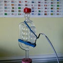
Introduction: IOT Homebrew Bubble Catcher Part 2
Internet of Things (IOT) is the buzz word of last year and will continue to proliferate in 2016. I will describe here how to connect my bubble counter described here and plot a dynamic, live graph to the internet.
I will be replacing the arduino uno device used in part 1 with an esp8266 nodemcu device. This has a wifi module built in, can be programmed like the arduino with the arduino ide and has a regular micro usb connector for easy hookup to your pc. We will use thingspeak.com to send our bubble interval data to. It will plot a live graph from your data, this excellent resource also allows you to use powerful matlab functions to manipulate data (eg curve filtting, dew point calculation for weather applications .. etc) . here we will just be plotting bubble interval data
Step 1: Wiring the Esp8266 and Optocoupler
Three wires need to connect the esp8266 to trhe opto coupler
esp8266 -- optocoupler
Vcc - Vcc
Gnd -- Gnd
D3 -- Data
Here I have my esp8266 connected to the opto coupler with dupont cables
nb the fritzning diagram shows an arduino device. I couldn't find a suitable fritzning part for the nodemcu esp8266 device I used.
Step 2: List of Parts
plus of course your fermatation vessel and sugary stuff you are fermenting
nb other suppliers* are available
Step 3: Setting Up Arduino Ide
Using the arduino ide on your pc upload this sketch: github link to my software
You will need to modify the settings on your arduino ide software to support your nodeMCU device.
ARDUINO IDE extension (adds support for NodeMCU boards to Arduino IDE)
Boards manager link: http://arduino.esp8266.com/stable/package_esp8266c...
How-To launch the Arduino IDE as normal and go into preferences enter the link above into the Additional Boards Manager URLs option you can then go to Tools Menu and under Boards select Boards Manager option you should now have an ESP8266 boards option you can now integrate into the Arduino IDE
Also, you will need to download the nodeMCU v1 driver here
Now select your board and upload speed:
Go to the Tools menu and set:
board type to: NodeMCU V1 (ESP-12E Module)
CPU frequency to: 80MHz
Upload speed: 115200
Port: usually com4 or com5 but could change depending how many ports you have used up previously.
nb you will need the following libraries installed for this sketch to compile:
ESP8266WiFi.h
WiFiClient.h
WiFiClientSecure.h
SPI.h
Wire.h
Step 4: IOT Setting Up ThingSpeak
We are going to use ThingSpeak to log and graph our bubble interval data.
- Sign up to create your account at ThingSpeak
- From the channel option, create a new channel
- Give it a meaningful name and name the data field appropriately
- make a note of you Write API Key and your Read API key for this channel
You are now ready to enter this write api key to your sketch
Step 5: Positioning the Sensor
I used a couple of elastic bands to position and secure the opto coupler to the bubbler. I found that it was a little tricky to align the sensor at first, especially if fermentation has just kicked off and it is slow. Once it is aligned, and bubbles are being reported on the
Tips for sensor alignment
Try to align the sensor so that it its path is just past the bottom neck of the bubbler tube (see red line in pic above) . This will help to prevent false readings. The sensor , helpfully has a red led on board which flashes when a bubble is detected in its path. I found it's better if the LED is on when there is no bubble and off when a bubble is detected (it works conversely, however its harder to align) Alignment is much quicker/ easier If you align the sensor when fermentation has got going (bubbles 2 secs or less apart) try it and see!
A bit of sugru on the bubbler can be used to fix the bottom position of the sensor for easy subsequent alignment. Only the top elastic band will be needed then. See the final photo. This works well
Step 6: Observing and Interpreting Thingspeak Graphs and Data .. Further Investigations
The first graph shows the bubble interval graph for day 4 of fermentation, the second for day 6 of fermentation.
The immediate observation is that the bubble interval is sinusoidal. This seems to match the temperature waveform shown in graph 3 shown on the yellow trace (slightly out of phase probably due to the position of my temperature sensor on my stainless steel fermenter. Its taped on the side of the fermenter, insulated with a sheet of polystyrene)
The period of temperature/ bubble interval sine waves appear very similar the interval behaviour is due to slight temperature variations. So ± 0.3°C (man 19°C) results in a bubble interval variation of ±75 secs (mean 125 secs) on day 6 of fermentation
Next time I'll position my temperature sensor in the heart of the wort (I have a glass carboy also with a thermowell that goes through the rubber bung.) I should be able to control the temperature to ±0.1°C. I wasn't expecting to observe such a big variation of bubble interval with small temperature variation.
Step 7: Further Work and Investigations
You may have noticed that I have included temperature readings of fermentation in one of my graphs. I have another device logging temperature and I've recorded and plotted data from this. It will be easy enough to add a onewire temperature sensor to the esp8266 device and I have the onewire code ready to go. If your interested let me know.
The initial investigations of graphs were involved with checking how significant a small variation of fermenting temperature is with co2 bubble interval. What my initial intention was to increase fermentation temperature slightly after the initial vigorous fermentation say 4 or five days after lag time.I'll still run some tests on this and decide whether this is a go'er.
Could controlling temperature based on co2 bubble interval give you better control in latter stages of fermentation, attenuate more reliably? or even produce nicer tasting beer ;)
A comment on my last instructable by ... suggested that this could be used for aquarium co2 monitoring. Watch for the final part in this series where I will explain how to integrate this with IFTTT which will alert you to certain defined events by email, text message, notification ..
**********************************************************************************
nb Do NOT base co2 bubble interval as a basis to stop fermentation and bottle. Use a hydrometer for this purpose and you should only bottle when you have a steady specific gravity reading close to your predicted final gravity.
**********************************************************************************


