

Introduction: Interfacing DS1307 I2C RTC With Arduino


In this tutorial i am going to show how to easily make a digital clock using DS1307 RTC module.RTC is Real Time Clock.Real time clock is used to keep record off time and to display time.It is used in many digital electronics devices like computers, electronics watches, date loggers and situation where you need to keep track of time.The advantage of real time clock is that it keeps record of time if the power is also not available.RTC has a CMOS battery.This CMOS battery is used to keep record of time when the power not available.This RTC will keep record of time for years without power since it uses very less power.
Step 1: Components Required

Microcontroller
- Arduino Nano
LCD
- 16 x 2 LCD
LCD interfacing board
- Three pin LCD interface Board
RTC Module
- DS 1307 I2C RTC
Wires
- Female to Female jumper wire -------9
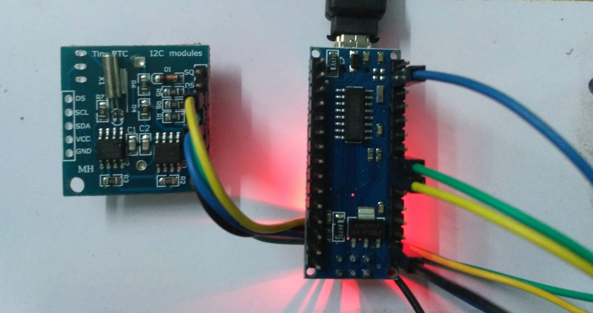
Step 2: Schematic Diagram

Step 3: Interfacing LCD


In the schematic diagram LCD is interfaced using only 3 pins.I had used 3 pin interface board to connect LCD to arduino.This interface board has shift register.Generally we interface LCD using atleast 6 pins.This is an old method.The new method to connect LCD is using 3 pin interface board.If you don't have this interface board,you can make it on your own.Click on below link to know how to create it.
Step 4: Setting the Time and Date in RTC

Upload the below code to set time and date.Uploading this code will load the time and date to RTC from your computer.After uploading the code open serial monitor to see the time and date.
NOTE
Don't use latest version of arduino IDE for programming.If you use latest arduino IDE, you cannot set time and date in RTC.You also need to add some libraries if you use latest IDE.I found problem with the latest arduino IDE.I strongly recommend to use arduino 1.6.1 IDE version.If you use this version you no need to add libraries because all the libraries were inbuilt in this version.I have also attached the libraries for latest arduino IDE users.
Program Code
#include<Wire.h>
#include "RTClib.h"
RTC_DS1307 RTC;
void setup ()
{
Serial.begin(9600);
Wire.begin();
RTC.begin(); // load the time from your computer.
if (! RTC.isrunning())
{
Serial.println("RTC is NOT running!");// This will reflect the time that your sketch was compiled
RTC.adjust(DateTime(__DATE__, __TIME__));
}
}
void loop ()
{
DateTime now = RTC.now();
Serial.print(now.month(), DEC);
Serial.print('/');
Serial.print(now.day(), DEC);
Serial.print('/');
Serial.print(now.year(), DEC);
Serial.print(' ');
Serial.print(now.hour(), DEC);
Serial.print(':');
Serial.print(now.minute(), DEC);
Serial.print(':');
Serial.print(now.second(), DEC);
Serial.println();
delay(1000);
}

Step 5: Displaying in LCD

Upload this code to display in LCD and i have also attached the program code for download.
Program Code
#include<Wire.h>
#include<RealTimeClockDS1307.h>
#include<LiquidCrystal_SR.h>
LiquidCrystal_SR lcd(6,5,9);
// Pin 6 - Data Enable/ SER, Pin 5 - Clock/SCL, Pin 9 -SCK
#define Display_Clock_Every_N_Seconds 10
#define Display_ShortHelp_Every_N_Seconds 60
String tz;
int hours = 0;
int minutes = 0;
int seconds = 0;
int dates = 0;
int months = 0;
int years = 0;
int ap = 0;
void setup()
{
Serial.begin(9600);
lcd.begin(16,2);
pinMode(A3, OUTPUT);
digitalWrite(A3, HIGH);
pinMode(A2, OUTPUT);
digitalWrite(A2, LOW);
}
void loop()
{
RTC.readClock();
ap = RTC.isPM();
if(ap == 1)
{
tz = "PM";
}
else
{
tz ="AM";
}
lcd.home();
hours = RTC.getHours();
minutes = RTC.getMinutes();
seconds = RTC.getSeconds();
dates = RTC.getDate();
months = RTC.getMonth();
years = RTC.getYear();
lcd.print(hours);
lcd.print(":");
lcd.print(minutes);
lcd.print(":");
lcd.print(seconds);
lcd.print(" ");
lcd.print(tz);
lcd.setCursor(0, 1);
lcd.print(dates);
lcd.print(":");
lcd.print(months);
lcd.print(":");
lcd.print(years);
delay(250);
lcd.clear();
lcd.home();
lcd.print(hours);
lcd.print(" ");
lcd.print(minutes);
lcd.print(" ");
lcd.print(seconds);
lcd.print(" ");
lcd.print(tz);
lcd.setCursor(0, 1);
lcd.print(dates);
lcd.print(" ");
lcd.print(months);
lcd.print(" ");
lcd.print(years);
delay(250);
lcd.clear();
}
