

Introduction: LCD Screen With 74HC595 and Keypad Module


This project is to hook up both an LCD screen and a keypad to your Arduino with the help of the 74HC595 shift register. Using both the LCD screen and keypad otherwise would not be doable with only the 13 Arduino pins.
*references were used to piece all of this together*
Step 1: Materials

For this project, I used:
- LCD Screen
- 74HC595 Chip
- Potentiometer
- Membrane Switch Module (Keypad - Not Pictured)
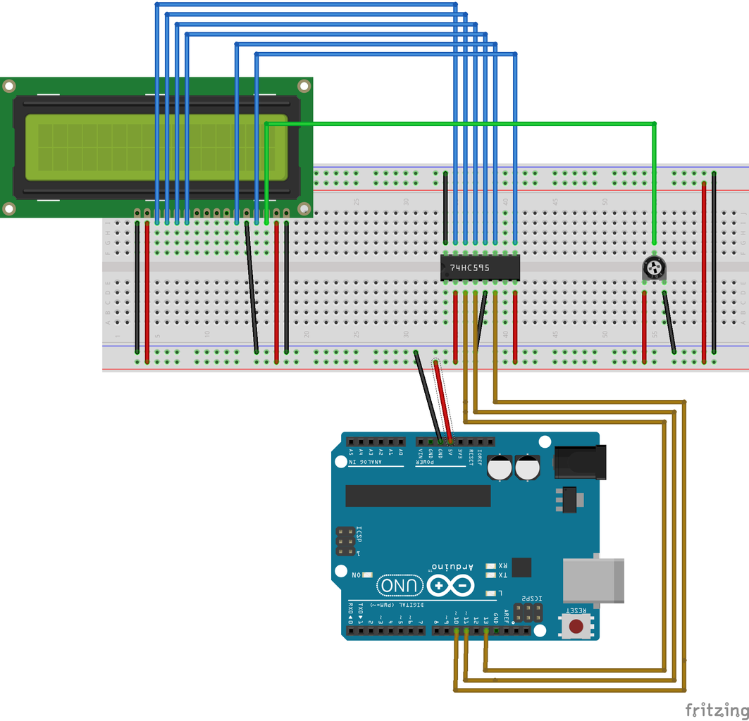
Everything is positioned where I wanted it on the breadboard before I started working on the wiring.
Step 2: Connecting the LCD Screen Using 74HC595 Shift Register

I started connecting from the left, beginning at pin 16 on the LCD screen. Pin 16 is connected to the ground rail, and pin 15 to power. The next four pins will be connected to the 74HC595 chip.
- LCD pin 14 to 74HC595 pin 7
- LCD pin 13 to 74HC595 pin 6
- LCD pin 12 to 74HC595 pin 5
- LCD pin 11 to 74HC595 pin 4.
The next four pins on the LCD screen will have no attachments.
LCD pin 6 to 74HC595 pin 3.
LCD pin 5 will be connected to the ground rail, and pin 4 will go to 74HC595's pin 1.
LCD pin 4 will connect to the potentiometer. Finish up the connections for the LCD screen by connecting pin 2 to power, and pin 1 to ground.
Step 3: Connecting 74HC595 to Arduino

Before connecting the 74HC595 to the arduino, I finished the potentiometer's connections by connecting the left side to power, and the right to ground. In addition, I added power and ground connections for each side of the breadboard.
Pin 8 on the 74HC595 chip will be connected to ground (which is why I used the extra connections for each side of the breadboard). Pin 10 of the 74HC595 will be connected to power.
Pins 11, 12, and 14 of the 74HC595 chip are connected to pins on the Arduino. Pin 11 was connected to pin 13 on the Arduino.
ERROR IN FRITZING DIAGRAM: The diagram shows that 74HC595's pins 12 and 14 are connected to 11 and 10. This is wrong, and will prevent words from printing to the screen. Pin 12 on 74HC595 should connect to 10, and pin 14 should go to the Arduino's pin 11.
74HC595's pin 13 will be connected to ground, and pin 16 will go to power.
Step 4: Connect GND and 5V (and Test)
Last, connect the breadboard's power and GND to the Arduino. Now the LCD screen should run using only three pins on the arduino as opposed to the usual six.
Before connecting the keypad, test out the LCD screen to see that it runs. You will need to download a new library for LiquidCrystal (which will only use a single value -- the position of the latch pin -- where the original would have used six). The following test code was taken from the earlier link.
#include < SPI.h >

#include < LiquidCrystal.h >
//remove the spaces above

// Initialize the LCD screen using the latch pin
LiquidCrystal lcd(10);

void setup() {
  // set up the LCD's number of columns and rows:
  lcd.begin(16, 2);
  // Print a message to the LCD.
  lcd.print("hello, world!");
}

void loop() {
  // set the cursor to column 0, line 1
  // (note: line 1 is the second row, since counting begins with 0):
  lcd.setCursor(0, 1);
  // print the number of seconds since reset:
  lcd.print(millis()/1000);
}
Step 5: Add the Keypad + Code
The keypad did not come as an available part in the Fritzing diagram, so I only showed the wires and pins I used.
From left to right, the keypad pins are 8, 7, 6, 5, 4, 3, 2, and 1.
I connected keypad pins 8, 7, 6, and 5 to Arduino pins 5, 4, 3, and 2, respectively.
Keypad pins 4, 3, 2, and 1 are connected to Arduino pins 9, 8, 7, and 6, respectively.
In order to run the Keypad code, you will need to include the Keyboard library. It should be available if you install a library through your Arduino IDE.
#include < Keypad.h >
//remove the spaces

const byte ROWS = 4; //four rows
const byte COLS = 4; //four columns
//define the cymbols on the buttons of the keypads
char hexaKeys[ROWS][COLS] = { {'1','2','3','A'}, {'4','5','6','B'}, {'7','8','9','C'}, {'*','0','#','D'} }; byte rowPins[ROWS] = {5, 4, 3, 2}; //connect to the row pinouts of the keypad byte colPins[COLS] = {9, 8, 7, 6}; //connect to the column pinouts of the keypad//initialize a NewKeypad Keypad myKeypad = Keypad( makeKeymap(hexaKeys), rowPins, colPins, ROWS, COLS);
void setup(){
Serial.begin(9600); }void loop(){
char key = myKeypad.getKey(); if(key) { Serial.print(key); } }
Step 6: Finishing Code

Using pieces from the example codes to initialize the keypad and LCD screen, I wrote the rest of the code to do some not-quite-so-impressive actions.
void setup(){<br>   Serial.begin(9600);
    lcd.begin(16, 2);
    lcd.print("Press any key to");
    lcd.setCursor(0,1);
    lcd.print("change screens.");
}<br>
In the setup method, the LCD screen will print out the statement "Press any key to change screens." on the two lines.
The loop method will wait to run until a key is pressed, and the screen will change. From there, the screen changes are set to happen by delays. The code exits with a scroll that uses a for loop. (i is set to be less than 16 due to the 16 spaces on the LCD screen).
 void loop(){<p>  char key = myKeypad.getKey();
  if(key)
  {
    lcd.clear();
    lcd.print("Now what?");
    lcd.setCursor(0,1);
    lcd.print("--Good question.");
    delay(2000);
    lcd.clear();</p>
    lcd.print("Time for a");
    lcd.setCursor(0,1);
    lcd.print("dramatic exit.");
    delay(2000);

    for(int i = 0; i < 16; i++)
	{
           lcd.scrollDisplayLeft();
           delay(100);
   	}

  }
 }
The intention was to use a switch statement or some other conditional logic to accept an answer via keypad input and print values to the screen depending on the choice. This kept resulting in a forever loop that either wouldn't pause to accept the input, or it would skip over the new conditional logic entirely and start at the beginning of the loop statement again. Next time!


