

Introduction: LED Array Program


More by the author:


About: My name is Logan Carlson, I am a recent graduate of Florida Polytechnic University with a degree in Computer Engineering. I try to build all the time and post my projects, but it is time consuming so I have no…
This is my first instructable with electronics, I have made one on Website development though. I'm still trying to get the hang of creating instructables and working with electronics but I am pretty happy with this project, being that its my first one. If you have any comments or suggestions please comment and let me know so I can improve. Here is a video of the final product in the dark.
Step 1: Materials Needed


For this project I used an Arduino UNO but any microcontroller would work you would just have to tweak the code and the layout of the components. The other materials you will need to complete this project will be:
- (x5) LEDs ( I used blue, red, and green but you can use whatever colors you want also more)
- (x1) Microcontroller (Arduino or other)
- (x2) Breadboards (One can be used it might just be messy)
- (x1) Potentiometer (Variable Resistor)
- (x1) 9V power supply
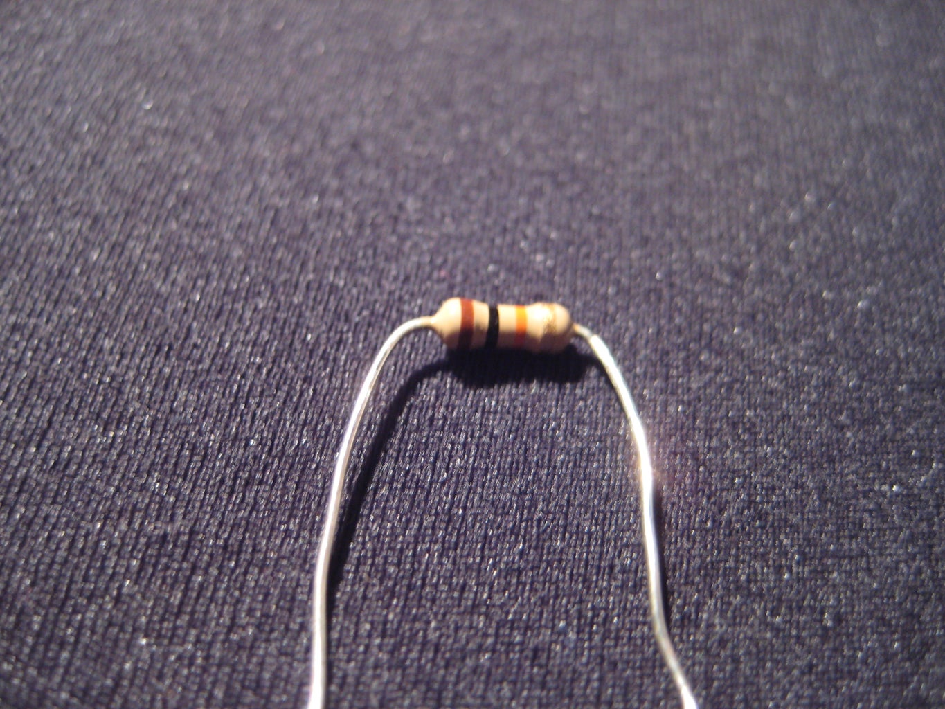
- (x5) 1K Ohm Resistors
- (x5) 10K Ohm Resistors
- (x4) Tactile Buttons (Or any other button i just used them because they are small)
- (x5) LEDs ( I used blue, red, and green but you can use whatever colors you want also more)
- (x1) Microcontroller (Arduino or other)
- (x2) Breadboards (One can be used it might just be messy)
- (x1) Potentiometer (Variable Resistor)
- (x1) 9V power supply
- (x5) 1K Ohm Resistors
- (x5) 10K Ohm Resistors
- (x4) Tactile Buttons (Or any other button i just used them because they are small)
Step 2: Wiring the LEDs and Buttons
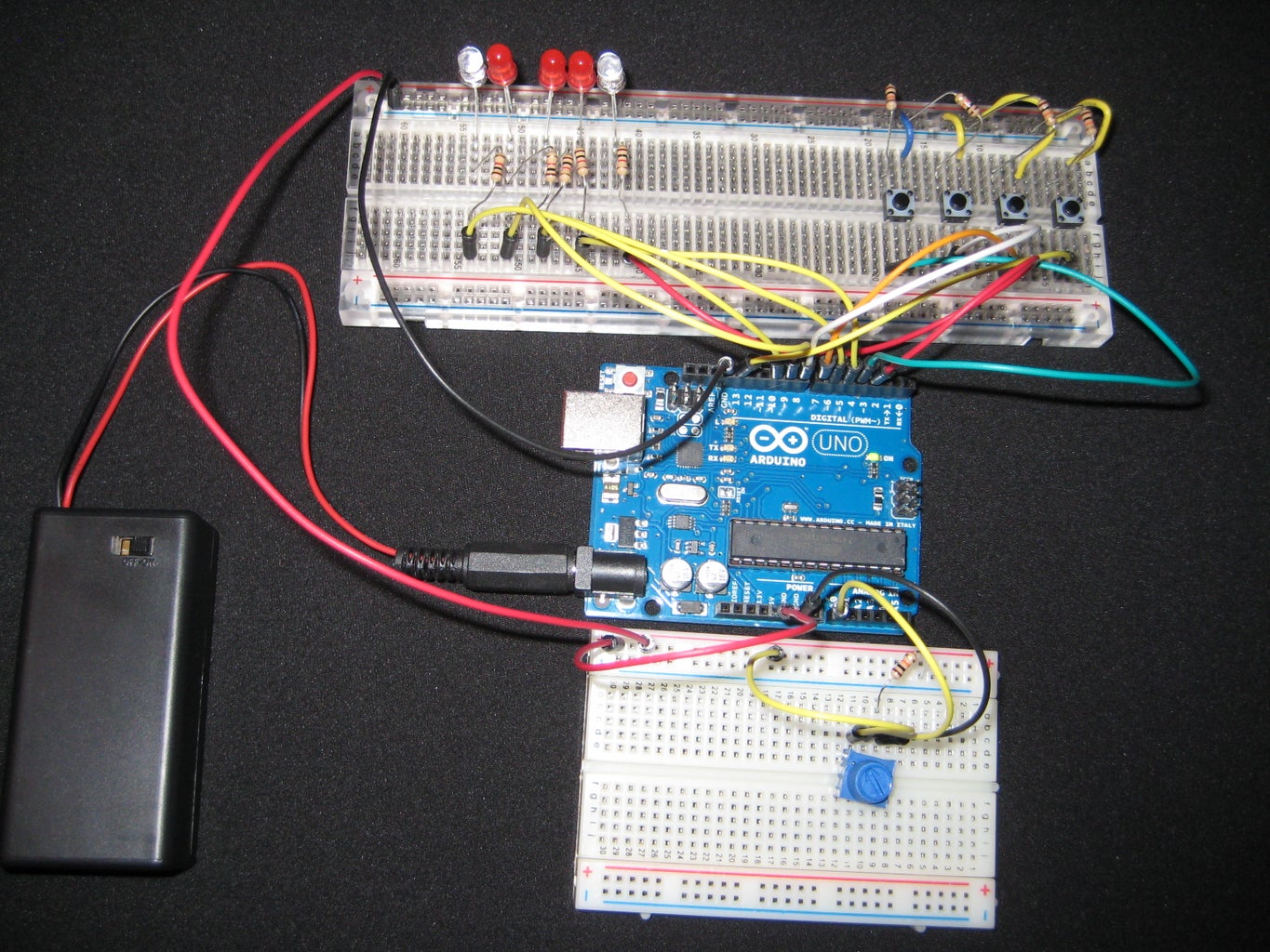

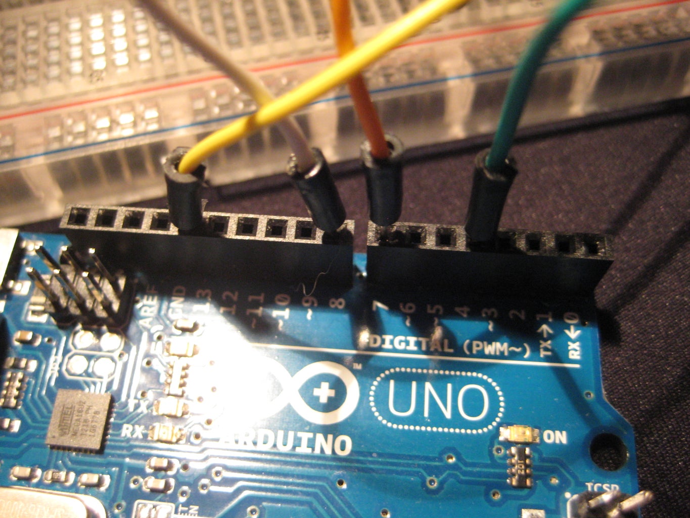

For this step you will need the Arduino, your LEDs, both types of resistors, buttons, and wire.
Follow the instructions on the images for details on connections (You'll have to click on them, or just continue reading). If it is hard to understand, I apologize in advance; just comment and I will try my best to help you solve your problems.
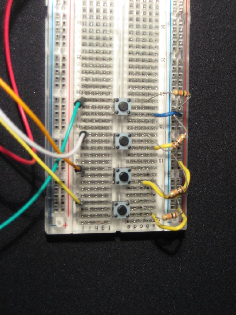
You will need at least 4 tactile buttons and they will need to be placed on the middle of the breadboard spaced out. Then the buttons need to be connected to the 5V rail on the breadboard with regular hookup wire. Next to this pin, on the button, a 10K Ohm resistor needs to connect the button to the GND rail. Then directly opposite the GND pin a jumper, or regular wire, needs to be connected to the correct pins on the Arduino. The buttons are out of order as to placement and pins. They need to be placed, not in any particular order, on pins 4, 7, 8, and 13. Then you are done with the button portion of the setup!
For the LEDs I chose to use three red, and one blue and one green. These need to be placed in the correct order for the program to work!! Connect each LED's anode (short lead) to the GND rail on the breadboard. Then connect each one's cathode to a 1K Ohm resistor and connect it to the opposite side of the breadboard. The resistor's opposite lead needs to be connected to either a jumper or any other wire. Then this wire must be connected, IN ORDER FROM LEFT TO RIGHT, to pins 3, 5, 6, 9, and 10. Each of those pins is a PWM pin, meaning Pulse Width Modulation, this will allow the LEDs to be controlled in many different ways.
Next, the 5V, red, rail on the breadboard needs to be connected to the 5V pin on the analog side of the Arduino. And the GND, blue, rail needs to be connected to the Arduino's GND pin on the digital side.
Follow the instructions on the images for details on connections (You'll have to click on them, or just continue reading). If it is hard to understand, I apologize in advance; just comment and I will try my best to help you solve your problems.
You will need at least 4 tactile buttons and they will need to be placed on the middle of the breadboard spaced out. Then the buttons need to be connected to the 5V rail on the breadboard with regular hookup wire. Next to this pin, on the button, a 10K Ohm resistor needs to connect the button to the GND rail. Then directly opposite the GND pin a jumper, or regular wire, needs to be connected to the correct pins on the Arduino. The buttons are out of order as to placement and pins. They need to be placed, not in any particular order, on pins 4, 7, 8, and 13. Then you are done with the button portion of the setup!
For the LEDs I chose to use three red, and one blue and one green. These need to be placed in the correct order for the program to work!! Connect each LED's anode (short lead) to the GND rail on the breadboard. Then connect each one's cathode to a 1K Ohm resistor and connect it to the opposite side of the breadboard. The resistor's opposite lead needs to be connected to either a jumper or any other wire. Then this wire must be connected, IN ORDER FROM LEFT TO RIGHT, to pins 3, 5, 6, 9, and 10. Each of those pins is a PWM pin, meaning Pulse Width Modulation, this will allow the LEDs to be controlled in many different ways.
Next, the 5V, red, rail on the breadboard needs to be connected to the 5V pin on the analog side of the Arduino. And the GND, blue, rail needs to be connected to the Arduino's GND pin on the digital side.
Step 3: Wiring Up the Potentiometer

I have the potentiometer on a separate breadboard but it could easily fit with the LEDs and buttons on a long breadboard. Again refer to the images for instructions, and if you don't understand, I will try and help.
The next piece to the setup is a small potentiometer. This, on my project, is placed on a seperate breadboard from the LEDs and buttons. (I will probably change that later though.) The breadboard must also be connected to both 5V (done by connecting it to the other breadboard's red rail), and the blue, GND, rail. The left, according to the picture, pin on the potentiometer is connected to the red rail on the breadboard. The middle pin should be connected to analog pin A0, and the left pin needs to be connected to GND by a 10K Ohm resistor. Make sure the GND rail is connected to the GND port on the Arduino's analog side. And then you're done with the electrical part of it!
The next piece to the setup is a small potentiometer. This, on my project, is placed on a seperate breadboard from the LEDs and buttons. (I will probably change that later though.) The breadboard must also be connected to both 5V (done by connecting it to the other breadboard's red rail), and the blue, GND, rail. The left, according to the picture, pin on the potentiometer is connected to the red rail on the breadboard. The middle pin should be connected to analog pin A0, and the left pin needs to be connected to GND by a 10K Ohm resistor. Make sure the GND rail is connected to the GND port on the Arduino's analog side. And then you're done with the electrical part of it!
Step 4: Programming
The programming portion is fairly simple. It is a little bit confusing as of right now but I am working on cleaning it up to make it more readable. There is a link to the code at the bottom.
Attachments

Step 5: Onto a Perf Board!


After having had the project on two breadboards I decided I would attempt at putting all of it onto a perf board. After many failed attempts, I finally got it all together. Next, I'm going to try and put it all in an altoids tin, or two, so it can be more portable. After getting everything working and soldered together, I hot glued it all to keep it in place and to keep from having any unwanted wires connecting.
