

Introduction: LED String Control

This tutorial covers getting started with LED light strings. I originally started by looking for a way to replace a standard incandescent light string on a Christmas tree.
For me, getting started required many sites and videos. Hopefully this guide will help you move on to the interesting parts more quickly.
Once you’ve started with a controller and a single light string, there are many directions you can take this. After building the controller, this guide will help you move to:
- Programming with Arduino editor
- Adding new effects and more lights
- Controlling the LED string from mobile device or home automation
- Integrating into a bigger light show
Step 1: Gather Materials


Parts needed:
- LED lighting kit (link)
This kit includes a WS2811 LED string (5V version), a 3A power supply, and a pre-made controller. There’s enough here that you can make sure everything works before following this guide.
The 5V version was chosen because that voltage can also power the Arduino.
- Wemos D1 mini controller (link)
This was chosen for small size, wifi connectivity and ease of wiring. Also, I already had one to experiment with.
- Power connector (link)
Needed to connect power supply directly to light string. Many in the package, but you need 1 male connector.
- Tactile button switch (link)
Size: 6 x 6 x 5mm, 4 Pin. Many in the package, but you only need one.
- Additional lights (link)
As needed. Be sure you’re buying the 5V version. See instructions below if you want to power multiple strings.
Step 2: Assembling the Controller


To start, you need the 3-wire pigtail that comes with the LED light string. You can find the right wires by seeing how the connector attaches to the string. The wire with the dashes is the negative, the middle is the data line, and the remaining outside wire is positive.
To wire up the D1 controller, make the following solder connections:
- Solder positive (probably red) to the 5V pin
- Solder negative (probably white) to GND pin
- Solder data (probably green) to D2.
- Use hot glue on the wires and board (to make it sturdier)
To attach the switch, solder:
- One side to the 3.3V pin
- One side to the D7 pin
- Solder D7 directly to D8 (e.g. bridge the pins)
- Cut off remaining unused pins
The switch is wired to 3.3V and D7 since it fits well directly on the board. However, D7 floats on the D1 mini and so can’t detect state changes by itself. To make it work, solder D7 to D8 so that D7 is pulled high on open. The code in the attached Arduino sketch shows how to use the switch.
Step 3: Assembling the Light String

In this step, we’re going to wire the power directly to the string in a different way. This will power both the string and the D1 controller at the same time. Another benefit of this approach is that the D1 remains powered when disconnecting from the USB.
Attach the power connector to the loose wires on the end with the pin receptacle. Watch positive and negative (see Step 2 to find each).
Step 4: Programming the Controller

To prepare your Arduino environment, follow these directions:
- https://www.instructables.com/id/Programming-the-WeMos-Using-Arduino-SoftwareIDE/
- Follow this guide to install the FastLED library https://www.arduino.cc/en/guide/libraries
To get started, use the attached INO program.
This code does the following:
- Uses FastLED library to animate the LED string
- Demonstrates different lighting effects
- Uses button push to change effects
- Keeps the brightness at 50%, which is bright enough and reduces the current draw.
- Sets the color temperature for the type of string we’re using.
- Limits the LEDs to 50, which should be changed when adding additional strings
Note that white is generated by turning on red, green and blue in equal amounts on the string. That makes white look different than the white-only LED strings sold for Christmas trees. We can take advantage of this to set the standard color to something more natural and resembling incandescent bulbs. I found that "CRGB::Khaki" gives a more natural color.
- FastLED animation library http://fastled.io/
- Simple example at https://github.com/FastLED/FastLED/wiki/Basic-usage

Step 5: Put It All Together

To start using the new controller, follow these steps:
- Open the Arduino sketch
- Use the IDE to load it onto the Wemos D1 mini
To confirm it's working:
- Check that LED on D1 board lights
- See the string light up white
You can cycle through the effects by clicking the button soldered to the D1 mini.
Step 6: Additional Lighting Effects

This is a great set of examples in using the FastLED library.
Adapt these effects to the Arduino sketch.
Sparkle is fun effect. For that one, change the code to set the selected LED to go black rather than bright white.
//modify:<br>//#define MAX_SEQUENCE 4
//
//add these lines into switch statement:
//case 4:
//  SnowSparkle2(CRGB::Khaki, CRGB::Black, 20, random(100,1000));
//  break;
//add these lines at the end of the file:
void SnowSparkle2(int val, int val2, int SparkleDelay, int SpeedDelay) {
  setAll2(val);
  int Pixel = random(NUM_LEDS);
  leds[Pixel] = val2;
  FastLED.show();
  FastLED.delay(SparkleDelay);
  leds[Pixel] = val;
  FastLED.show();
  FastLED.delay(SpeedDelay);
}
Step 7: Expanding the Light String
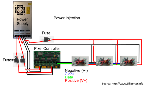
Strings can be extended using the attached plugs. However, the voltage will fall off after about 2 strings. This can be fixed by running 5V wires in parallel with the LED light string. You can use the loose wires to accomplish this--pay attention to the positive/negative polarity.
Example of string wiring on this page:
- http://www.billporter.info/2017/01/07/the-engineers-guide-to-diy-computer-controlled-holiday-lights/
Good explanation of wiring and voltage drop at:
This Instructable also includes a good tip on wrapping LEDs in electrical tape. Scotch Super 88 (3/4” width) works well.
In addition, the MAX_LED in the Arduino sketch must be changed when you add more LEDs.
Step 8: Remote Control

To control the string remotely, use Blynk. Reference at:
Add the required Blynk code to the Arduino sketch. You can configure the Blynk app to:
- Change effects
- Use the RGB zebra to change color
- Control the brightness
See the attached Arduino sketch for changes to include Blynk. Steps:
- Add Blynk libraries to Arduino
- Sign up for Blynk account
- Download app to phone
- Create new project. This will create an authorization code for that project.
- Modify the attached sketch to include auth code, wifi name and wifi password
- Use Arduino editor to load into D1 mini.
Attachments
Step 9: Connecting With Home Automation

You can control the string by adding an MQTT client to the Arduino sketch. Install an MQTT broker on your home automation (e.g. OpenHAB or Home Assistant).
More information at:
Step 10: Making a Light Show

Inspiration at https://www.evilgeniuslabs.org/tree-v2
Pixel location in XLights https://www.instructables.com/id/LED-Christmas-Tree-With-Video-Projector-Rasp-Pi/
Explanation of DMX protocol https://learn.sparkfun.com/tutorials/using-artnet-dmx-and-the-esp32-to-drive-pixels/all
Artnet library https://github.com/rstephan/ArtnetWifi
Explanation of what actually is happening https://www.youtube.com/watch?v=hl-HUa5BOPM
Step 11: Do More

Do It Yourself Christmas http://www.doityourselfchristmas.com/wiki/
Full manual with complete explanations https://auschristmaslighting.com/threads/auschristmaslighting-101-manual.1889/


