

Introduction: LUX II - the Second External Pc Power Button


born out of laziness (and now carelessness)...
LUX II
LUX II is used to externally control your computer's power state by acting as if it were your computer's power button - except it is on your desk!
It is the second version of the popular LUX - with 43k views and 500+ likes it is one of my most popular instructables yet. As a user of the original LUX, I also felt that some changes needed to be made to the design to get it working nicely.
Let's go!
Step 1: Gather the Materials!
I will assume a lot in this instructable, mainly what tools you will need - this is because personal preference and availability influences it alot.
The main materials you are going to need is a single strip of 30x12mm wood.
Along with that you will need some small nails, an LED (and resistor), some USB extension leads and of course, a button!
This means that the LUX II costs around ~ $10 AUD or $7 USD. (as of 2015)
As for tools, all you really need is something to cut with, something to solder with, and something to nail with.
Some other tools you might use are a drill and a belt sander.
Step 2: Assembly, Part 1 - Cutting the Pieces

I had to split the Assembly part of this guide into multiple parts, simply because it makes it easier when following it.
PART 1 - CUTTING THE PIECES
This is the part where you guessed it, you cut the wood. In the images is a handy table that I used to label each of the parts and their respective sizes; this makes it a lot easier later on when figuring out what parts go where.
It's simple really, read the table, cut the pieces and move onto the next step.
Step 3: Assembly, Part 2 - the Base


I believe trying to explain how to assemble something is really hard without pictures, it's like trying to build something by listening to someone tell you how to do it - it just doesn't work. Most (or always) people want you to SHOW them how you did something.
So that is why most of these 'assembly' style steps will be mostly pictures - now mind you that means the pictures have to be good. I have included scans of my original drawings alongside pictures from when I was actually building it. The diagrams are (somewhat) faded from the scanner however you get the general idea.
So now, to assemble the base, see the pictures!
A little guide to the drawn diagrams:
- Numbers with inside squares represent the piece number (or ID) from the previous step's table (see how it's handy now?)
- The big circled numbers are the ordering of the step (1,2,3... so forth)
- Nail placing is included on the diagrams.
Step 4: Assembly, Part 3 - Sides

This step is an easy one.
You are just making the sides of the button that will hold the actual "button" piece of wood in. (this is made in the next step)
Just follow the pictures above!
Step 5: Assembly, Part 4 - the Button

An important note on this step, make sure to drill the hole in the exact middle of the bottom of the button.
This hole needs to be the size of the push-button that is going to be put into it.
Step 6: Assembly, Part 5 - the Final Smash (or Assembly...)


The final step of assembly is quite easy, simply:
- Get the piece you made in Part 1 & Part 2 and nail it in the center from the bottom.
- Gather the pushbutton you are using, and all of the wooden pieces, and then put the pushbutton onto the part you just made - now put the outer square ontop of the piece you just made and slot it through, now get the 'button' wood piece and push it down into the slot and align it so it is flush with the top. Mark where the outside wood sides are.
- Removed the pushbutton and the wooden 'button'
- Align the outer wood sides with the mark you just made and nail it in.
Done!
Now to soldering...
Step 7: Solder


- Get your USB extension lead and chop the female end off.
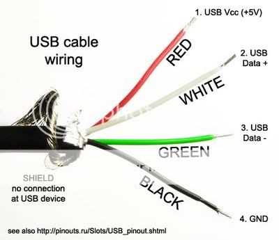
- Splice the inside wires - they should be red, black, white and green as per this diagram - if it isn't you have a non standard USB cable (you can figure it out it is just harder).
- Get your LED and pushbutton and solder some wires onto them so that they are long enough to poke out the back of the LUX II where the hole you drilled is.
- Solder these wires to their respective wire on the MALE end of the USB extension lead (remember the diagram) - be sure to use either some shrink-wrap or a small piece of tape.
This wiring should be red -> LED+, black -> LED-, white -> pushbutton, green -> pushbutton
DON'T FORGET THE RESISTOR FOR THE LED WIRE!
Then make sure to secure the wires by hot gluing them.
Now grab the other end of the USB lead, the one with the female plug.
- Get 2 female to female breadboard wires and cut them both in half to have 4 pins.
- Splice the wire end of the USB extension lead - the colors should be same as the diagram shown before.
- Solder a half female breadboard wire to each of the spliced wires from the USB lead.
- Heat shrink or sticky tape them (so they don't short)
If you made the original LUX and are upgrading, you will need to replace the part that connects from USB to the header pins that go into your motherboard.anyone else, just ignore this...
Step 8: Assembly
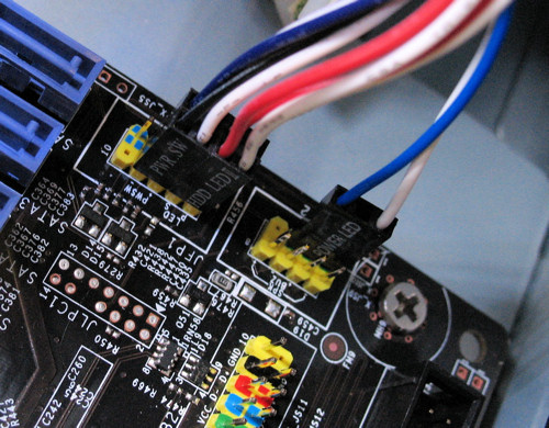
This is a super simple step - you first need to locate the part of your motherboard that has what is known as the front panel connector.
Some images if you are confused: (note these pictures are not mine)
(hint, look for lots of double female header pins - also don't confuse these with the Audio and USB pins)
After you have found that, then you need to locate two specific cables - one usually called "POWER SW" which is the power switch, and one (or 2 singles) that say "POWER LED" (also maybe '+' and '-') - this is the LED that goes to the front of your computer case.
Once you have found those, grab the female plug we hacked and unplug the previous connectors and plug the new ones in. Test it by connecting the male plug from the LUX main body to the female USB plug.
Tip - remember the wiring diagram we followed?
If the button works but the LED doesn't, you probably have the polarity backwards, simply switch them around and you are all good to go.
If the wire is too short to reach your desk, then simply grab some more USB extension leads - that's the whole reason we used them!
Guess what? There is no programming used with the LUX II so you are DONE!

Participated in the
Epilog Contest VII

Participated in the
Make It Glow! Contest


