

Introduction: Light Nib

This project is an intent to join two visual arts on which creativity and technique are always present: calligraphy and photography. Accorrding to wikipedia, calligraphy is a visual art related to writing; as for the photography, it literally means "drawing with light". If you are into lettering or light painting this can be useful to you.
This Instructable describes how to join these two areas with electronics and some programming. Instead of using ink and paper to write nice calligraphy letters, we are using LEDs to paint/write letters and the canvas will be our photo frame. There are some basic techniques that will be described for calligraphy and photography, but for the most part, some extra references will be listed so you can dig into more details if you want.
In Photography, light painting is using long exposure photography to create magnificent light effects with a portable light source and loads of experimentation. The tool created to draw calligraphy with light is something I'd lke to call: 'Light nib'. It is heavily based on Arduino.
If you prefer to draw complete images, you can take the fully automatic approach such as this great projects did: LightScythe runs on Arduino, so storing big or many pictures is something to take into account. The results are something similar to the Persistent-of-Vision (PoV) effect. The guys at Adafruit did a great job on sharing this tutorial on how to create similar results using a raspberry Pi (a platform where storage is not an issue).
The 'light nib' is not an automatic tool. Instead, it is light source that reacts to commands and gestures that the artist gives to the nib. Just like a real nib, it can change its color and react to hand gestures to modify the width of the stroke. The final result: calightgraphy.
Step 1: The Idea Behind the Light Nib: Calligraphy


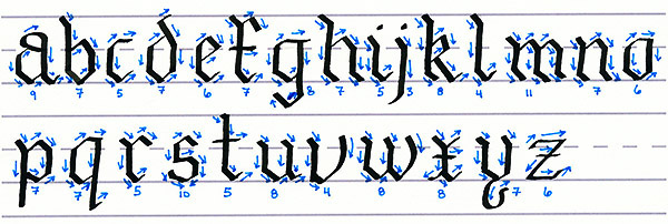
Calligraphy has been around for centuries. It was used before the printing machine was invented. Calligraphers were the people in charge of creating unique pieces of art using writing. I started practicing some calligraphy and then the idea of the light nib hit me.
The angle of the nib is very important when practicing calligraphy, let's use an IMU!
Inks can be of any color visible by man, let's use RGB LEDs!
Unfortunately it is impossible to cover all there is about Calligraphy on one instructable. However, if you are interested in Callipgraphy the book from Margaret Shephert named Learn Calligraphy the complete book of lettering and design is a truly easy and inspiring way to get into this beautiful art. I bought the book on Google books.
The basic rules are important, because they bring order when using the light nib:
- Letters are written with one or several strokes! You can find educational calligraphy alphabets, indicating the order and direction of the strokes. Like this one, you get one in the booklet when you buy a Pilot Parallel Pen. To simulate this, the light nib requires an ON/OFF button to simulate strokes.
- Five lines dictate the size of any letter, lower or upper case.
- The baseline serves as the reference to every letter.
- The midline will be the maximum height for the main body of the lower case.
- The descender and ascender mark the maximum length of the lower and upper extensions of the lower case, respectively.
- Some letters have a capital height, others use the ascender line to limit the capital height.
- Many letters use a straight nib and they have different sizes, depending on the size of the letter and the style of the calligrapher. Because of this I chose a bar of LEDs.
- Every Calligraphy style defines an angle of the nib to be used during writing. Some letters may require you to change the angle of the nib. Here's where the IMU becomes useful.
My two cents on how to get you started on Calligraphy. Buy one 3.8mm parallel pen from Pilot, they are cheap, and that's it! I assume you already have one notebook and pencil. Optionally, get one Rhodia notebook, they work great with Parallel Pens.
Remember, practice makes perfect! Calligraphy is no exception.
A laser cutter would be awesome to bring calligraphy from 2D to 3D. The tangible world!
Besides, there are some projects in robotics I'm working on, that would receive a great push with a laser cutter and 3D printer.
More information on typography and all the lines that define a typography.
Step 2: The Scenario


To make it usable, the light nib had to be ergonomic and ready for right and left handed people. Another important thing to take into consideration is the arrangement of all things when taking the long exposure photo.
To make the writing more natural the light nib, held by the user, projects the light backwards. The user can concentrate on writing, paying attention to limiting lines previously defined on the canvas. The camera is located on the back, the user can write normally and their movements will be captured by the camera. Of course, the light on the room has to be completely off, so that the camera only captures the light coming from the LEDs.
The images on this step represent the scenario, the way the light nib is held, a photograph of how it looks on a dark room and lastly, a little video showing how it works.
Step 3: Materials


The components required to build a light nib are basically:
- A programmable Micro Controller Unit (MCU).
- One Inertial Measurement Unit (IMU).
- One bar of LEDs.
- Any kind of toggle switches.
- A portable power source.
The past list is too general and can be sufficient for the most experienced makers out there. When choosing all components, it is important to make sure that the power levels on every component are compatible (3.3 or 5 volts). The light nib only uses 5V components, here is the detailed list:
- Arduino Pro mini, the 5V version.
- ArduIMU V3, it only works with 5V.
- 8 led Neopixel bar. Works with 5volts, requires a 1000uF capacitor and one 470 ohm resistor.
- Micro switches. Coupled with some pull-up resistors (330 ohms will suffice).
- The light nib described here uses a USB cable and a cell-phone portable charger as a power source.
Portable cell phone chargers are very common these days and they basically consist of one big battery. Because power travels through two of the four lines of a USB cable, an old cable was repurposed to power the light nib.
If you run into trouble on how to interface components with different power levels, you can take a look at this nicely written PDF.
ArduIMU has been discontinued in Sparkfun, but there are plenty of options to measure absolute position. My recommendation is this IMU breakout board from Adafruit. It really looks awesome, it is 3.3V and 5V compatible, leaving you a plethora of compatible MCUs to chose from.
Step 4: The Electric Diagram.

The electric diagram is very simple.
- Power comes from a usb cable that has been repurposed. When connected to a portable cell phone charger, it will provide the power to the light nib.
- The power lines are connected to all electric components:
- ArduiIMU
- Arduino
- NeoPixel
- The serial TxD line from the ArduIMU is connected to the TxD line in the Arduino. In order to receive the orientation data.
- As explained by the Adafruit tutorial, the Neopixel is connected trough a data line and some passive components to the Arduino.
- The mechanical switches have a pull up resistor.
Step 5: The Software

The software running on the Arduino is very straight forward. But first, it worth mentioning the following:
- The ArduImu has a serial communication port. The Arduino receives serial packages from the IMU that then decodes and translates into numeric values denoting the orientation of the board. This part of the code would have to be modified if you use other IMU, specially if you choose an IMU that communicates with I2C or SPI.
- The NeoPixel library has been developed by Adafruit and it is very easy to use. Here's the tutorial.
The arduIMU wasn't easy to setup, but this tutorial helped a lot. The code shared on that page had some issues, let's assume it was because of the firmware version running on the ArduIMU. After some debugging It worked nicely.
The light nib has 2 switches to interact with the user and turn it on or off.
What the software does is:
- During setup, the code configures: the Input pins to read the switches, the serial port to receive data from the ArduiIMU v3 and the pins to control the NeoPixel.
- Once in the loop section of the code:
- The readPacket() function receives and verifies the code received from the IMU. It returns true if the packet is valid, false otherwise.
- If a valid packet has been received, the state of the switches is read with the function ReadInputs(). This function enumerates all possible combinations of the switches. For two switches, the total combinations are 2^2=4. The enumeration starts with 0, this indicates all switches are off, this is used to power off the LEDs.
- The combinations is decoded using a switch instruction, apart from the off condition, there are 3 more combinations used to trigger other patters of the light nib.
- Once the corresponding pattern has been drawn on the LEDs, the loop starts again.
You can have as many switches as you want to trigger different light effects. Adding a third would give you the possibility to have 2^3=8 possible combinations. But pushing that many buttons while drawing can be difficult, but still a possibility. The flow chart attached to this step, describes what has been discussed.
The Zip file includes three folders for you sketchbook directory:
- ReadBinaryArduIMUV3- The code to receive and decode the packages from the ArduIMU in the Arduino.
- NeoPixelTest- The code shared by Adafruit to get started with NeoPixel. The NeoPixel library is not included.
- LightNib- The full code to get the light nib running, using the hardware described here.
Attachments

Step 6: Putting Everything Together.


To put everything together, two premanufactured PCBs were used. They are united with a straight angle header.
- The first board carries the arduino pro mini, the arduimu, the two switches and one usb cable for power. The arduino and the arduimu are mounted on the first PCB with female-headers, this makes it easy to reuse these boards in future projects.
- The second board carries the neopixel and their corresponding components, a 1000 uF capacitor and one 470 ohm resistor.
If you will follow the idea here presented, be extra careful when defining the lines you are using to transmit power to the second board through the 90 degree header.
When connecting the usb cable, pay attention to the colors, black and red. If you are not sure, use one multimeter and connect the other end of the cable to a wall charger for smartphones. Of course, you have to make sure that none of the cables are in contact when plugging it in.
It would be cool to make a 3D printed vessel for this strange shaped device.
Step 7: Results! (After Some Practice) :D


For "light painting" photography you will basically need a camera with manual settings and a tripod. It would be useful if you have an off-camera flash, but it's not completely necessary to get you started.
You'll need to be in complete darkness to get the best results and a good advice is to wear black clothes and black gloves. You won't need to use the flash at the beginning.
Basic steps to do light painting:
- Set up your tripod on a stable surface.
- Set your camera to:
- Aperture mode (A) tag on Nikon and (Av) Canon cameras.
- Autofocus.
- ISO: 100
- Aperture: F/22
- Shutter speed: 30 seconds (you could vary this later)
- When the person that is going to write is standing in front of the camera, press the shutter button halfway down to start the autofocus, then, press all the way down to start taking the photograph.
- When you finish your writing, stay away from the framing area and wait for the camera to finish taking the picture. Don't move the camera or press any button until it is done.
- Look at the results and make adjustments in the previous settings only if necessary.
- Repeat and keep trying until you get the best results. You’ll just need to vary your shutter speed based on the amount of light and the complexity of your painting.
After many experiments using the light-nib, the work paid off! :D
The cool thing is that you and create as many patterns as you want by interpreting the IMU data!
Changing color is one simple move, the next is to vary intensity, turning on and off some LEDs... whatever you want.
Keep on drawing!

Participated in the
Full Spectrum Laser Contest 2016


