

Introduction: LinkIt One Tutorials - #11 HC-SR04 Ultrasonic Distance Sensor


For this tutorial I am going to interface a HC-SR04 ultrasonic distance sensor to a LinkIt One board.
The HC-SR04 works using an echo system - a tiny pulse of high frequency noise (way above human hearing range) is emitted from one side of the board, it bounces off a nearby object and returns.
When the return signal is received we do some maths which basically amounts to dividing the time taken between the pulse being sent and received by 2 and then dividing that figure by 29.1 to tell us how far the sound travelled and therefore how far away an object is.
Step 1: Materials Required


LinkIt One board
HC-SR04 Ultrasonic Distance Sensor
Try your favourite auction site
Li-Ion battery
Breadboard
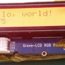
Grove LCD RGB Backlight display
4 Male to male jumper wires
Step 2: Uploading the Sketch to the LinkIt One Board

Download the attached Arduino sketch distanceSensor.ino and load it into the Arduino IDE.
Connect the LinkIt One via micro USB and upload the sketch to the board.
Disconnect the USB lead from the LinkIt One.
Attachments

Step 3: Connect the Parts to the LinkIt One


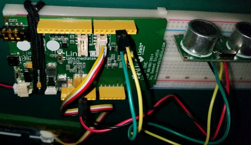


Connect the Grove LCD RGB Backlight display to the Grove port on the LinkIt One marked "SCL SDA 5V GND"
Insert the HC-SR04 distance sensor into 4 columns of the breadboard with the front facing outwards. I have used columns 40 through 43.
Column 40 has the GND pin
Column 41 has the Echo pin
Column 42 has the Trig pin
Column 43 has the Vcc pin
Connect a black male to male jumper wire from column 40 (GND) to GND on the LinkIt One.
Connect a green male to male jumper wire from column 41 (Echo) to D2 on the LinkIt One.
Connect a yellow male to male jumper wire from column 42 (Trig) to D3 on the LinkIt One.
Connect a red male to male jumper wire from column 43 (Vcc) to 5v on the LinkIt One.
Ensure the BAT/USB switch on the LinkIt One is set to USB and plug the battery in.
Finally, switch the BAT/USB switch to BAT and go have some distance measuring fun.
Step 4: What Next?

The numbers tend to jump slightly.
How would you prevent them jumping?
If you connect the Vcc pin to 3.3v rather than 5v the sensor cannot judge distances as far as with 5v.
Ask yourself why.
Verify the distances recorded with a tape measure. Are they accurate?
If not, how can you make them more accurate?


