

Introduction: Linkit One Environment Monitor


I have built an environment monitor using the Linkit One board. This monitor can be placed remotely in the building and monitor motion and temperature at that location. The monitor also sends back its own battery level so I know if it needs recharging. Communications is handled by Wi-Fi included on the Linkit One. The data is sent to the Mediatek Cloud Sandbox where it can be viewed live and also a historical view is available. I am interested in the historical data to track motion in the area day and night.
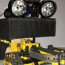
Step 1: Parts

Parts needed for this project
Linkit One board
Linkit One Battery (included with board)
Linkit One Wi-Fi antenna (included with board)
PIR motion sensor
DHT11 temperature and humidity sensor
10K resistor
DHT library for Arduino - here is one place you can get it https://github.com/adafruit/DHT-sensor-library
Step 2: Getting Started
MediaTek Linkit ONE is developed for wearables and Internet
of Things (IoT) devices, which using hardware and API similar to those offered for Arduino boards. So you can code on it by Arduino IDE just like on Arduino (I have found the Aruino IDE 1.6.5 works the best at this time). There is a website with a detail introduction of Linkit ONE and its SDK.
First you need to install the Arduino IDE on your computer, then follow the steps on the Mediatek website to install the Linkit One board libraries into the Aduino IDE.
You will also need to download the DHT11 library and go into the Aduino IDE under Include Library and use the install functions there.
Step 3: Wiring Up the Hardware


First I created a 5 volt bus and a ground bus on the breadboard by connecting them to 5 volts and ground on the Linkit One.
Then connect VCC and ground from the PIR motion detector to +5 volts and ground respectively, the out pin goes to digital pin 12 on the Linkit One.
The wiring for the DHT11 is shown above. Pin 1 is 5v (red) -- Pin2 (green) is the output and goes to digital pin2, it also has a 10K pullup resistor connected to 5v -- skip Pin 3 -- Pin 4 goes to ground.
Plug in the battery and Wi-Fi attenna that comes with the Linkit One.
That finishes the wiring.
Step 4: Software Code for the Linkit One
To learn how to write the code, I spent time looking at the weather station example at labs.mediatek.com and at the fine example on Instructables named Build a weather station by MediaTek Linkit One by Cavedu.
In both of these examples there is a lot of frame work code that handles the connection to the Mediatek Cloud Sandbox. I copied all the connection frame work code from these examples. I don't think they want you to write your own code, that is what samples and tutorials are for. What you have to change to make it work for your example is the following.
Wifi name of your router
Password of your router
Device ID - You will get this when you create a prototype and device in the Mediatek Cloud Sandbox. We will show that later.
Device key - same as above step
Sensor IDs - For each sensor in your hardware implementation there will be a unique id that you have to come up with. In my example the ids are temperature_display, battery_level and motion_binary. These device IDs and their data have to be put in the uploaddata string that goes to the server.
Attachments

Step 5: Setting Up the Mediatek Cloud Sandbox

Go to the Mediatek site and under DevTools and Resources find the Cloud Sandbox.
First you create a Prototype. The one shown above is my Station Monitor prototype. I created this by hitting the Add Data Channel button three times and creating three different data channels for my three inputs. When you are satisfied that you have all your data channels, press the button Create test device
Step 6: Work With Test Devices

Now you should have a device like the one above. You can always find the devices you have created under Development/Test Devices. Notice the DeviceId and DeviceKey that need to go in the Arduino IDE code. That is how your Linkit One finds the right device in the sandbox. Once you get your code running on the Linkit One you can see your sensor values live here.
Notice the three little squares in the right upper corner of each data channel. Touch on this and a popup menu will come up and allow you to see historic data of your sensor value. The next panel will show this.
Step 7: Historic View of Data Channels

This is the same test devices panel with the data channels set to historic. This what I was looking for. I want to be able to monitor different locations in the building at night for activity and also check on the temperature. The actual usage would be to check on security making their rounds and monitoring temperature for good resource management.
Step 8: Live Display of Data Channels

This screen shows a live display of the data channels


