

Introduction: MCU-1: a Budget-conscious Intel Edison MCU Based Rover Toy Car. (Intel IoT)

Small video showing obstacle avoidance and few button based commands via bluetooth.
Step 1: Summary
This project will build a simple rover car which can be controlled by an android smart app using voice or button based commands remotely. The smart app connects to a bluetooth serial module on the rover car which in turn runs off of servos controlled by an application running on the Intel Edison MCU (micro controller unit).
The micro controller unit (MCU) on Edison is part of the SOC (dual atom core + the Minute IA based MCU). MCU runs a RTOS (Viper from WindRiver) which in turn runs an ‘MCU application’ which can do interesting things such as managing IO ports, collect and control sensor data, etc.
There is an excellent guide available here: Creating applications with MCU SDK: (https://software.intel.com/en-us/creating-applications-with-mcu-sdk-for-intel-edison-board) if you are new to MCU on Intel. The guide runs you through installing the MCU SDK (which is separate from the Eclipse SDK for the Intel Atom™ processor) and introduces you to building MCU applications.
This project builds a simple rover robot car mostly driven from the MCU (only the bluetooth connection is handled by arduino on the host CPU with commands forwarded to MCU for action). Since the MCU is a low frequency core (100MHz max) it will cost much less (in terms of energy consumption) to do similar things on it, rather than on the host Intel Atom™ processor (500MHz max).
The approach and emphasis here is to do an easy budget-conscious construct/take-apart project, built with as many things around the house as we can. With that spirit in mind, I have used a cardboard, 2-sided tapes, rubber bands to put the main chassis in place and then to ‘attach’ Edison, battery and breadboard driven circuitry to the chassis.
Step 2: Parts List.
- Cardboard
- 2 servos (https://www.foxytronics.com/products/68-springrc-sm-s4303r-continuous-rotation-servo )
- 2 matching wheels (https://www.foxytronics.com/products/269-2-5-8-plastic-black-wheel )
- Ball bearing for front roller (http://www.harborfreight.com/5-8-eighth-inch-roller-ball-bearing-67067.html )
- Battery (http://www.amazon.com/Poweradd-Pilot-12000mAh-Portable-Blackberry/dp/B00F4U49M6/ref=sr_1_fkmr0_2?ie=UTF8&qid=1432660658&sr=8-2-fkmr0&keywords=poweradd+model+pilot+with+lcd )
- Intel Edison with Arduino breakout board (http://www.adafruit.com/products/2180 )
- Small breadboard
- Ultrasonic Range sensor – HC-SR04 (https://www.foxytronics.com/products/132-hc-sr04-ultrasonic-distance-sensor )
- Bluetooth serial module – HC-05 (http://www.amazon.com/Innogear-Wireless-Bluetooth-Transceiver-Arduino/dp/B00JP05S6C/ref=sr_1_1?ie=UTF8&qid=1432661180&sr=8-1&keywords=cz-hc-05+gomcu )
- 220uF capacitors (http://www.adafruit.com/products/2192 )
- Wires; rubber bands; zip-ties; scotch tape; 2-sided tapes, etc.
Step 3: Chassis


Chassis / Servos / Front ball bearing.
I chose a simple cardboard based chassis with the servos stuck to it using 2 sided tapes reinforced with rubber bands. There are many ways you can go here from ordering plexi-glass pre-cut chassis to using zip-ties instead of 2-sided tapes – let your creative juices flow. The above choices work as long as your rover is roving over smooth surfaces.
Step 4: Battery, Board


Mount this free-form and then later secure it to the chassis using rubber bands – surprisingly this works pretty well (remember we plan on using this on smooth surfaces only – adjust the attach according to your plans).
Step 5: Pin Mappings

We will be (primarily) be using pin 0,1,2,3, 5,6 on the breakout board.
Step 6: Breadboard -- Ultrasonic Range Sensor (HC-SR04)
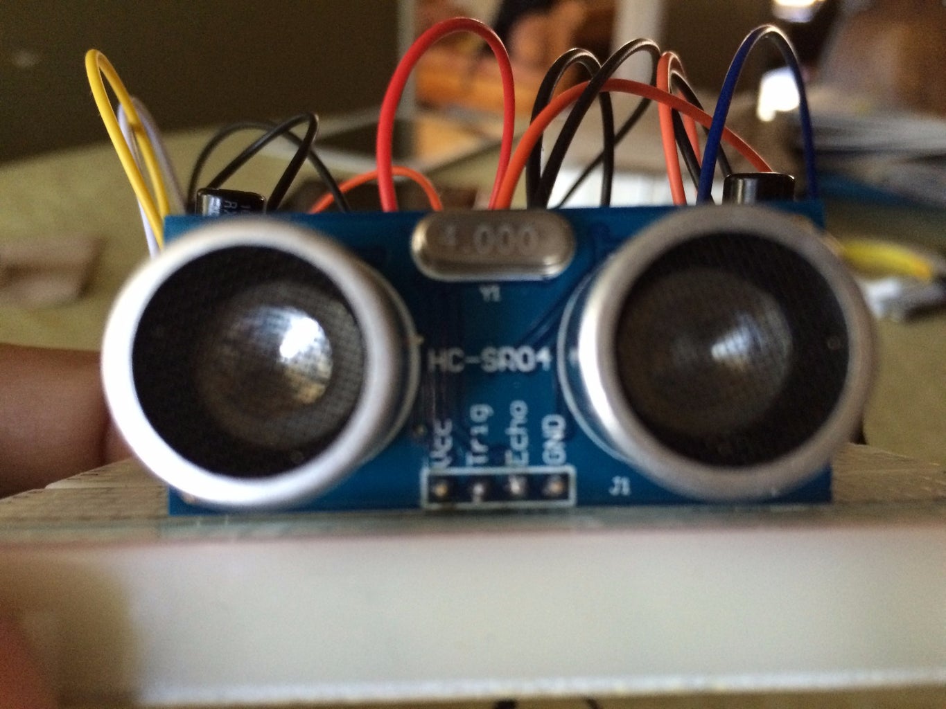

Start setting up your circuitry – above shows ultrasonic sensor hc-sr04 statically mounted onto the breadboard (options include putting it on top of a motor to scan left / ahead / right sides when figuring out where to move next). Wiring is pretty simple – vcc, trigger, echo and ground.
Step 7: Breadboard -- Servo Connections


Here we show the wiring needed for connecting the servo cable -- 3 pin connection coming out from the servo – red (vcc), black(ground) and in my case white(signal). The picture (Servo wiring 1) shows the 220uF capacitor connected between vcc/ground – this is needed for each servo in order to avoid the brownout issues. Since we are using the same battery source to power the servos and the board; on sudden rover turn of directions, there can be spikes of current draw which can cause the board to recycle if we don’t provide a sizeable capacitor (220uF works just fine in our case). The pictures show wiring for 1 servo without the servo cable attached (Servo wiring 1); with the servo cable attached (Servo wiring 2) and then both the servo cables attached.
Step 8: Breadboard -- Bluetooth Serial Module (CS-HC-05)


The above pictures show the connection for the bluetooth module – we only use vcc,ground,txd, and rxd – txd/rxd go to 0rx,1tx pins on the Edison board respectively.
Step 9: Code -- MCU Application.
{{{

<p>#include "mcu_api.h"<br>#include "mcu_errno.h"</p><p>#define INPUT 0
#define OUTPUT 1</p><p>int echoPin = 128; //2
int trigPin = 13;  //5
int blinkPin = 40;  //13
int leftMotor = 0; //pwm3
int rightMotor = 2; //pwm6
unsigned long startT, endT, elapTime, stopTime, tmpTime1;
unsigned long counter = 1;</p><p>void pulseIn2(unsigned int state, int timeout) {
	int count = timeout;
	while (gpio_read(echoPin) != state && count > 0)
		count--;
}</p><p>void turnLeft(int leftMotor, int rightMotor, int duration) {
	pwm_configure(leftMotor,  2000000, 20000000);
	pwm_configure(rightMotor, 2000000, 20000000);
	pwm_enable(leftMotor);
	pwm_enable(rightMotor);
	mcu_sleep(duration);
}</p><p>void turnRight(int leftMotor, int rightMotor, int duration) {</p><p>	pwm_configure(leftMotor,  700000, 20000000);
	pwm_configure(rightMotor, 700000, 20000000);
	pwm_enable(leftMotor);
	pwm_enable(rightMotor);
	mcu_sleep(duration);
}</p><p>void go(int leftMotor, int rightMotor) {</p><p>	gpio_write(blinkPin, 0);</p><p>	pwm_configure(leftMotor,  700000, 20000000);
	pwm_configure(rightMotor, 2000000, 20000000);
	pwm_enable(leftMotor);
	pwm_enable(rightMotor);</p><p>}</p><p>void reverse(int leftMotor, int rightMotor, int duration) {
	gpio_write(blinkPin, 1);</p><p>	pwm_configure(leftMotor,  2000000, 20000000);
	pwm_configure(rightMotor, 700000, 20000000);
	pwm_enable(leftMotor);
	pwm_enable(rightMotor);
	mcu_sleep(duration);
}</p><p>void stopMotor(int leftMotor, int rightMotor) {
//	host_send((unsigned char*)"Stopped\n",8);</p><p>	pwm_disable(leftMotor);
	pwm_disable(rightMotor);
}</p><p>void incrStopTime(int reset) {
	if (tmpTime1 > 0) {
		stopTime += (time_ms() - tmpTime1);
		if (reset) tmpTime1 = 0;
		else tmpTime1=time_ms();
	};
}</p><p>void mcu_main() {
	unsigned int runMotor = 1;
	unsigned char btInput = 0;
	char buf[64];
	int len;
	unsigned long distTraveled;
	/* your configuration code starts here */
	startT = time_ms();
	elapTime = time_ms();
	stopTime = 0;</p><p>	gpio_setup(echoPin, INPUT);  //in
	gpio_setup(trigPin, OUTPUT);  //out
	gpio_setup(blinkPin, OUTPUT); //out</p><p>	while (1) {
		mcu_sleep(50);
		btInput = 0;
		len = host_receive((unsigned char *) buf, 64);
		if (len > 0) {
			btInput = (char) buf[0];
			switch (btInput) {
			case 'S':
				gpio_write(blinkPin, 1);
				stopMotor(leftMotor, rightMotor);
				tmpTime1 = time_ms();
				runMotor = 0;
				break;</p><p>			case 'A':
				gpio_write(blinkPin, 1);
				go(leftMotor, rightMotor);
				runMotor = 1;
				incrStopTime(1);
				break;</p><p>			case 'L':
				gpio_write(blinkPin, 1);
				turnLeft(leftMotor, rightMotor, 95);
				go(leftMotor, rightMotor);
				runMotor = 1;
				incrStopTime(1);</p><p>				break;
			case 'R':
				gpio_write(blinkPin, 1);
				//    reverse(1000);
				//    stopMotor();
				turnRight(leftMotor, rightMotor, 95);
				go(leftMotor, rightMotor);
				runMotor = 1;
				incrStopTime(1);</p><p>				break;
			case 'B':
				gpio_write(blinkPin, 1);
				turnLeft(leftMotor, rightMotor, 95);
				turnLeft(leftMotor, rightMotor, 95);
				go(leftMotor, rightMotor);
				runMotor = 1;
				incrStopTime(1);
				break;
			default:
				break;
			}
		}
		if (runMotor) {
			gpio_write(trigPin, 0);
			gpio_write(trigPin, 1);</p><p>			gpio_write(trigPin, 0);</p><p>			pulseIn2(1, 10000);
			long startTime = time_us();</p><p>			pulseIn2(0, 10000);
			long endTime = time_us();
			int duration = endTime - startTime;</p><p>			int distance = duration / 2 / 29; //29.1?</p><p>			if ((distance != 0) && (distance < 15)) {
				reverse(leftMotor, rightMotor, 95);
				stopMotor(leftMotor, rightMotor);
				turnLeft(leftMotor, rightMotor, 95);
				go(leftMotor, rightMotor);
			} else {
				go(leftMotor, rightMotor);
			}
		}
		endT = time_ms();
		if ((endT - startT) > 10000) {
			incrStopTime(0);
			startT = time_ms();
			distTraveled = (endT - elapTime - stopTime) * 12 / 60000;  // approximate feed driven based to static RPM of servos.
		};
		len = mcu_snprintf(buf, 16, "%d\n", distTraveled);
		host_send((unsigned char*) buf, len);
	}
}</p>
}}}
Attachments

Step 10: Code -- Arduino Bluetooth Communication.
{{{

<p>int btInput;<br>int startT, endT, count = 0;
int feet;
FILE* fp;</p><p>void setup() {
  // put your setup code here, to run once:
  Serial1.begin(9600);
  Serial.begin(9600);
  startT = millis();
  system("echo 0 > /tmp/edRover");
}</p><p>void loop() {
  // put your main code here, to run repeatedly:
  endT = millis(); count++;
  if (endT - startT > 11000) {
    fp = fopen("/tmp/edRover", "r");
    startT = millis();
    fscanf(fp,"%d",&feet);
    Serial1.println(feet);
    fclose(fp);
  }
  delay(500);
  system("read feet < /dev/ttymcu0; echo $feet > /tmp/edRover");</p><p>  btInput = 0;
  if (Serial1.available() > 0) {
    btInput = Serial1.read();
    Serial.println(btInput);
  }</p><p>  switch (btInput) {
    case 'S':
      system("echo 'S' > /dev/ttymcu0");
      break;</p><p>    case 'A':
      system("echo 'A' > /dev/ttymcu0");
      break;</p><p>    case 'L':
      system("echo 'L' > /dev/ttymcu0");
      break;</p><p>    case 'R':
      system("echo 'R' > /dev/ttymcu0");
      break;</p><p>    case 'B':
      system("echo 'B' > /dev/ttymcu0");
      break;</p><p>    default:
      break;
  }</p><p>}</p>
}}}
Attachments
Step 11: Code -- MIT App Inventor 2 (Visual Programming)


MIT App Inventor is an excellent cloud based smart app development tool. I used this to create the android smartapp that does remote communication with the rover car (via voice or button based). Please go here to learn more about the tool: http://appinventor.mit.edu/explore/get-started?
Once you are more familiar with working your way through the tool environment -- take a look at the entire 'source' code for the smart app we use in this project.
The images show the entire designer and blocks view for the android smartapp. You can use this to build and install apk on your smart device running android to control the robot.
Step 12: Code -- Init Scripts to Setup Pins for MCU.
https://software.intel.com/en-us/node/557356
Download the init scripts from the above link -- we will be using primarily the digital and pwm ones.
Write your own wrapper shell script using above downloaded scripts.
e.g.
{{{
echo "on" > /sys/devices/pci0000\:00/0000\:00\:17.0/power/control
<path_to_your_downloaded_scripts>/pwm/init_PWM.sh
<path_to_your_downloaded_scripts>/gpio/init_DIG.sh -o 13 -d output
<path_to_your_downloaded_scripts>/gpio/init_DIG.sh -o 2 -d input
<path_to_your_downloaded_scripts>/gpio/init_DIG.sh -o 5 -d output
}}}
Step 13: Putting It All Together.
- Build and download the arduino sketch onto the board.
- Build and download the MCU application code to Edison MCU.
- On reboot -- Ensure the rover won't run away once the below init scripts have run -- lift it off its wheels.
- Login and run the init scripts to setup gpio (I have a wrapper script I run -- using the step above).
- At this point you should have a simple obstacle avoidance rover working -- there is no remote control ability.
- Build and install the apk generated by the App Inventor 2 onto your android smart device.
- On your device pair with the Bluetooth module (default passkey is 1234).
- Startup your app and connect with the paired bluetooth connection.
- At this point you should be able to remotely control the rover with voice or manual key presses.


