

Introduction: Make a Programmable RGB LED Infinity Mirror With Arduino


This Instructable shows you how to make a framed one-way mirror that reflects individually programmable RGB LEDs into a mirror. This creates the illusion of an infinite tunnel of pretty lights with an on/off power switch.
This looks intimidating!
I started this project knowing nothing about electronics. I did have some simple coding experience but you can copy/paste code to get the effect you see above.
Is there an easier or different way to do this?
Yes, the LEDs could be remote controlled (no Arduino), not controlled at all ("non-addressable"), or manually controlled with potentiometers on a breadboard. Instead of the one-way mirror, you could use plexiglass or acrylic with window tint instead. Or you could put stuff inside the frame which would also reflect infinitely.
What is specific/unique about this infinity mirror vs. others?
- Arduino controlled (customizable code for the LEDs)
- Outside access to the USB A-B port of the Arduino and power supply jack
- An actual one-way mirror instead of acrylic + one-way vinyl tint
- Custom frame
- Pretty big infinity mirror (more lights, bigger power supply needed, bigger/heavier in general, more expensive). The overall cost was ~$320 with an extra meter of LEDs and other small parts left over.
Step 1: Tools, Materials, Electronics, Vendors


Tools
- Soldering iron
- Lead-free solder
- Electrical tape
- Scissors
- Measuring tape
- Wire strippers*
- Rubber insulated clamp*
- Vice gripsº
- Hammerº
- Black markerº
- Mirror cleaner + microfiber towelº
- Double sided tapeº
- Drill + drill bitsº
- 8 ankle bracketsº
- Rubber bumperº
- Offset clipº
- Screwsº
- Wood glueº
- Chiselº
- Wooden spacersº (about .45" x .45" x at most as long as the frame itself)
- Wood miter/trimmerº
- 1 can of Rustoleum 2X Satin Black spray paintº
*These weren't necessary but they can be helpful
ºThese were for the build and assembly of the frame. I negotiated the pricing of the frame with the frame store (credits to Zephyr Designs in Brattleboro, VT) to also be able to use their space, tools, and materials and get help for this step.
Materials
The dimensions of the mirrors will define your LED strip length which impacts how many power supply amps (A) and capacitor farads (uF) you'll need. LEDs and power supplies can get pricey too. You can play around with dimensions here: http://framedandmatted.com/builder.
- One-way mirror (dimensions matching the mirror)
I was blessed by the LED gods and found one sized at 25x35" in a thrift store for $14 after I was quoted $174 by a local glass shop for the same thing. A cheap alternative is plexiglass with a one-way mirror tint.
- Mirror
I got a 24x30" mirror for free from a local framing shop after I was quoted $68 by a local glass shop for the same thing.
- Frame
I paid $140 for the build, materials, and assembly of the frame and $5 for the spray paint at the hardware store. The frame includes the moulding (4 sides), wooden spacers + vinyl taped flat ankle bracket to secure the mirrors, LED strip, and arduino + capacitor, plywood boards, screws, etc. If you want to hang the mirror, you'll need two steel plate hangers with a steel cable with end loops.
Electronics
- Neopixel RGB LED strip ($25/meter)
- For a 24x30" mirror, I needed 108" of strip or 2.75 meters.
- individually programmable or "digitally addressable"
- black colored backing or "PCB"
- 60 LEDs or pixels/meter
- weatherproof silicon casing or "IP67" not needed, but came with the ones I ordered from Adafruit
- Arduino Uno R3ª ($25)
- Standard A-B USB cableª ($4)
- Prong/Prong Wiresª ($6)
- In-line power switch ($2.50)º
- Terminal block adapter ($2)
- 4700 uF capacitor ($2)
- 2-pin JST SM plug + receptacle cable ($0.75)
- 5V 10A power supply ($25)
ª To get these, I purchased the Arduino Budget Pack ($35) so I could also spend some time experimenting and get a better understanding of circuits before moving onto the LED strips, have variable length wires with connectors, etc.
- º This is not necessary–I wanted to be able to turn on/off the lights from this switch instead of plugging the power supply in/out of the wall.
Step 2: Wiring the Circuit


DON'T DAMAGE YOUR LEDS!
These articles helped me avoid that mistake:
1. Cut the LED strip to your desired length.
Because my mirrors are 24x30", I needed (2 x 24") + (2 x 30") =108" or 2.75 meters of strip. Along the strip, you can see solid straight white lines with a scissors symbol next to it–you can use the scissors to cut along any of these lines.
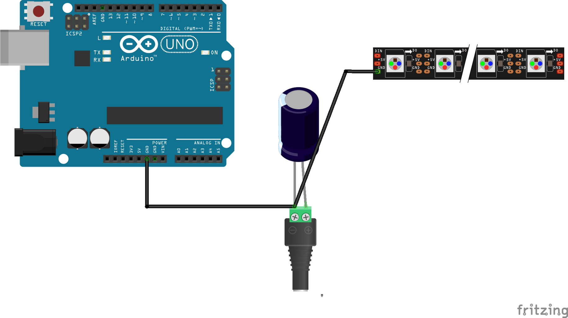
2. Connect the capacitor to the terminal block.
This step protects the LED strip from a sudden onrush of current (source). Connect the positive (longer) lead of the capacitor to the positive terminal of the green terminal block and the negative (shorter) lead of the capacitor to the negative side of the green terminal block. The negative lead is also indicated by the light blue strip on the side of the capacitor with large "–" symbols along it.
3. Connect ground between the Arduino, LED strip, and power.
This involves two connections. I used a jumper wire with connectors to connect Arduino's ground pin (next to Arduino's 5V pin) to the negative side of the terminal block. The other connection was made up of two pieces:
A) The tail wire of the socket JST SM In-line power wire connector soldered onto the LED strip's ground. A photo of my very DIY soldering set up is attached but also an example video is available here. Make sure that the LED strip's arrows are pointing AWAY from this wire.
B) A jumper wire's end in the corresponding head pin of the connector mentioned in 2A and the other end in the negative side of the green terminal block.
4. Connect +5V.
I soldered a jumper wire on the +5V part of the LED strip (again, LED strip's arrows should be pointing AWAY from this wire), connecting the other end to the positive part of the green terminal block.
5. Connect data.
I soldered the other tail wire of the socket JST SM In-line power wire connector to Din of the LED strip. Then, I put one end of a jumper wire into the corresponding head pin of the connector and the other end in the positive part of the green terminal block.
6. Add power.
Plug the USB cable into the Arduino and the USB port of a computer. Plug in the in-line power switch and power supply into the green terminal block DC adapter and into a wall outlet. The Arduino "ON" LED should light up.
Now if we want the LEDs to light up, we need to get some code onto the Arduino...
Step 3: Coding the Arduino


TEST YOUR LEDs
1. Install Arduino's Software.
Go to https://www.arduino.cc/en/Main/Software. This application is where you'll be making code, checking it for errors, and uploading it to the Arduino: https://www.arduino.cc/en/Main/Software.
2. Add Adafruit's NeoPixel Library.
Go to https://github.com/adafruit/Adafruit_NeoPixel. Click the green "Clone or download" button to the right. Click on "Download ZIP".
3. Follow instructions.
From this tutorial, I followed video instructions to test my circuit (neglect the one in the video) and strip: https://create.arduino.cc/projecthub/glowascii/ard... but try adjusting the NUMPIXELS value according to the number of pixels on your strip, change the color, and try to turn off the lights in the same way to get a handle of concepts like:
- Hex triplets
- for loops
- Verifying, compiling, and uploading Arduino code
- RGB additive coloring.
When the TX and RX LEDs light up on the board, TX means there's data transferring from the Arduino to the computer and RX means there's data being received by the Arduino from the computer. Rad!
UPLOAD FANCY CODE
I decided to use the rainbow cycle code from here: http://www.tweaking4all.com/hardware/arduino/adru....
BUT HOW DO I MAKE IT PRETTY WITHOUT THE COMPUTER?
- Make sure you've uploaded the code you want on the Arduino.
- Turn off the power from the power supply.
- Remove the USB cable.
- Put one end of a new jumper wire into the +5V power pin of the Arduino and the other end into the positive part of the green terminal block.
- Turn on your power supply. Your LED strip should be running the code without a computer. Voilà!
Step 4: Building the Frame


The frame is made of 2 pieces of wood that are secured together with pocket screws. Here are its details:
- 24 x 30"
- With rabbets wide enough for a 1" gap between 1/8" thick one-way mirror and 1/4" thick mirror + 12.5mm LED strip with weatherproof silicone casing
Two coats of Rust-oleum's 2X Satin Black spray paint with overnight drying
Step 5: Assembling Everything Together


1. Spray paint the frame and spacers
- Two coats needed
- Let the frame dry overnight. Keep note of the minimum temperature needed to ensure drying and setting of the paint
2. Insert the one-way mirror. Wipe it down with window cleaner and a microfiber towel
4. Use wood glue to set wooden spacers on top of the one-way mirror.
5. Double stick tape the LED strip along the frame.
- The wires are kept in the corner of the frame.
- Chisel a little divot in the frame to hide the wires. This allows the next row of spacers and the mirror (#6 and #7 below) to fit the frame.
6. Use wood glue again to set more spacers on top of the LED strip.
- I used a black marker to make sure all exposed sides of the wooden spacers were black.
7. Place the mirror on top.
8. Place a piece of plywood on the mirror and secure with ankle brackets bent at 90º.
- I marked the exact same position across 8 ankle brackets and used a vice grip and hammer to bend them.
- Screw in 2 ankle brackets per side of the frame to keep the plywood in place.
9. Secure the arduino and capacitor with wooden spacers glued to the plywood board, a screwed in offset clip with a rubber bumper, and a screwed in black vinyl taped non-bent ankle bracket.
- Photo attached.
10. Place the second piece of plywood board and screw it into the frame.
Step 6: Concluding Thoughts
Possible Improvements
Right now, the Arduino is just running the rainbow cycle which was something I copy/pasted from somebody else. Some other cool options could be:
- Have the code cycle through different modes
- Write code that corresponds with a song
- Write code and adjust electronics to make it responsive to different frequencies, beats, or touch

Participated in the
LED Contest


