

Introduction: Make an Optical Disk Display


Every curious how DVDs work? Interested in learning some simple analog electronics? This Instructables will show you how to make an optical disk display project in only a few hours. What is an optical disk? An optical disk stores data/information and can be read or displayed using light.
You will learn about basic analog electronics, basic electronic optics, and various basic electrical components. You will be making a fun encoder, turning a digital light interface into an analog signal that controls a 7-seg display.
Step 1: 7 Segment Displays


A 7 segment display is an array of LEDs. 8 LEDs are used to create a pattern that looks like an '8'. Depending on which part of the 7-seg you light up, it can display any number from 0 to 9 and some letters (let L, A, S, H and more). Like RGB LEDs there can be common cathode and common anode 7-seg displays. We will use common cathode displays, which use two GND connections and 8 other connections to light up the individual sections of the display.
Step 2: Phototransistors


Phototransistors are light activated transistors. For this application, think of a transistor as a switch. When a voltage is applied to the base of the transistor, current flows from the collector to the emitter (we are using a npn transistor). In a phototransistor, we use light to trigger the base pin. So when light is shining on the sensor, current is allowed to flow. We will be using this as a switch for the 7-seg display. If there is light reaching the phototransistor, current will flow through the device and to the corresponding part of the 7-seg display.
There are two pins on the phototransistor, one is the collector and one is the emitter. The third pin is light!
Step 3: Motors


Motors are electromechanical devices used to move stuff. They are everywhere, from an animated holiday cards, to electric cars. We will be using a geared motor to turn our disk. The gears are necessary to slow down the speed of the motor. Geared motors come in a variety of speeds. Many start with a 12V motor and use gears to either speed up or slow down the rate of rotation. If you slow down the rotation, you will have more torque but less speed. If you speed up the rotation, you will have less torque but more speed. Things to keep in mind when you are designing your project!
Step 4: Optical Storage


Our machine closely resembles an optical storage device, like a Blueray disk or a DVD. An optical storage device works by bouncing a laser off of a surface and back to a sensor. If there is a 'pit' (a small burn hole in the material) the laser takes longer to bounce back to the sensor. Each pit that the laser senses is considered a 1. Every other value is a 0. Combine enough of these binary 1s and 0s and you have data, aka information. So to summarize, optical storage is a bunch of burnt pits in a disk. The pattern of these pits determines the information stored.
Step 5: Design


So how does all of this relate to our device? We will use cutouts instead of pits to allow light to pass through to sensors beneath the disk. The disk will be like a pizza with 28 slices, each having 8 cutouts. The cutouts in each slice will light up an individual section of the 7-seg. The disk is rotated using a motor so that each slice gets a turn controlling the 7-seg. 8 phototransistor sensors below the disk will sense the light being either blocked or allowed through. If there is a cutout and light is shining through, then current will be allowed to flow through the transistor and will illuminate the section of the 7-seg.
The second picture shows the disk with each color corresponding to a part of the 7-seg. If you cutout every color in one slice then the entire 7-seg will light up for the duration of that slice. If you cutout the purple part of the slice then the top element in the 7-seg will be illuminated. Cutout red and blue and the middle and bottom right section of the 7-seg will light up.
The simulation below shows the phototransistor array. Click one of the phototransistors and slide the dial. It simulates what happens when there is a cutout in the disk. When you slide the dial to the right you will notice the corresponding part of the 7-seg light up. The simulation also shows a motor with the speed controlled by a potentiometer. This is what controls the rate of rotation of the disk, which in turn controls how fast your message scrolls on the 7-seg.
What are the resistors for? Why not only use the phototransistors? The resistors are necessary to control the current through the phototransistor. This is important in making the sensor act like a switch. If you are interested in learning more, take a further look into transistors: https://learn.sparkfun.com/tutorials/transistors
Step 6: Parts and Tools


To make your optical display machine you will need the following:
Components:
- 8x Phototransistors (I recommend getting more, they are easy to break)
- 8x 8K ohm resistors
- 1x 7 Segment Display(common cathode)
- 1x Geared Motor
- 1x 10K ohm Potentiometer
- 1x 9V Battery
- 1x 9V Battery Connector
- 1x Manila Folder
- 1x Breadboard
- 1x M3 Bolt
- Wires
- Cardboard
- Base material (could be cardboard, Plexiglas, acrylic, etc...)
Tools:
- Exacto Knife
- Electrical Tape
- Color Printer
- Circuits.io
Step 7: Build the Electronics


Now lets build the electronics:
Plug in the phototransistors. The long lead should go into the positive rail. The short end should go into column 57, row a, b, c, d, or e. Put the next phototransistor 3 spots down, there should be two columns in-between every phototransistor.

Plug in the 8.2K resistors. One end should go in the same column as the short lead of the phototransistor. The other end should go into the ground rail. Make sure the leads of the resistors don't short anything!

Plug in the 7-seg display further down the breadboard.

Connect the phototransistors to the 7-seg using the following picture as a guide

Plug in the potentiometer below the 7-seg. Connect one lead to the ground rail and one to the positive rail (9V in this case). Then connect the motor's negative wire to ground. Connect the positive wire to the potentiometer's wiper pin of the potentiometer (this is often the middle pin but check the datasheet).

Plug in the 9V and you are done!

If none of the 7-seg lights up then you want to unplug the battery as there is probably a short.
If some parts of the 7-seg are not lighting up then the corresponding phototransistor might be broken or be plugged in wrong.
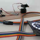
Here is a demo model I made for the electronics:
Step 8: Build the Mechanical Structure


Now lets build the mechanical structure:
Take your electronics and place it on the base of your choice. I used an acrylic sheet that I had lying around. Then tape the motor to this surface.

Then print out the attached picture of the disk. Cutout the circle part and punch a small hole in the center of the disk. Put the disk on the motor and secure it with the bolt. The bolt goes through the paper and screws into the motor shaft.

Next you want to put the breadboard and phototransistor array underneath the disk such that the phototransistors line up with the lines/rows of the disk. Once you get them lined up, secure the breadboard to the base.

Now we want to add some shielding to the phototransistors. This keeps stray light from bouncing into the sensor and lighting up the 7-seg accidentally.
To do this cutout a rectangular piece of cardboard with an intern cutout that is about the size of the phototransistor array. You might need two of these.

Tape one or two of these onto the motor such that it aligns with (and protects) the phototransistors.

Lastly, screw the disk back onto the motor and you are done!
This is an example of the finished product I made:

Step 9: Future Improvments and Conclusions

You can print out multiple disks and cutout a variety of different messages!
If you are looking to make the project better, cutoff the excess leads on each component such that it lies flat with the breadboard. It would also help to put this onto a proto-board or even a PCB. If you are interested in skipping the breadboard step, you can create a PCB from circuits.io. Other cool possibilities include 3D printing an enclosure, using larger 7-seg displays, and cascading multiple of these machines together to create a multi-letter display!


