

Introduction: Make Line Follower Robot in 5$


We all have faced a few set backs due to limited budget and reduced funding.
We can overcome this situation by innovating and using the cheap materials available to us.
Step 1: INTRO


The most basic concept in robotics is the line follower robot.
But this comes to us to at cost more than negligible.
To try new combinations and algorithms we need to cut the cost to down to negligible rate.
And be able afford failures helping us move forward from learning from our mistakes.
Step 2: ABOUT
This instructable is about reducing the cost and increasing programming skills.
Step 3: MATERIALS


`1) Attiny 13a - .81$
2) ir module - 0.49$
3) motors - 1.1$
4) Wheels - .33$
5) chassis -1.4$
6) H-bridge - .60$
7) wires - .11$
8) Jumper cables - .25$
9) 9v batteries - .16$
10) Arduino
11) Rubber bands- .02$
12) nuts and bolts
total cost <= 5$.
Step 4: CONNECTIONS


Start off with the connects.
Connect the ir module to the to the chassis and establish connection making sure the module is facing downwards to the ground.
Attach the motors with the help of nuts and bolts.
Once the motors and the ir modules are connected add the ball wheel.(purly for support).
Add wheels to complete the hardware of the body.
Step 5: ATtiny 13a Programming
To reduce the cost of the line follower robot we use attiny 13a.
Which is a very low cost micro controller.
We use the Arduino as the ISP(in system programmer) to program the attiny13a.
The ATtiny13 is a 8 pin micro controller,with 3 PWM pin and 2 Analog pins .
But in this tutorial we use only digitalWrite and digitalRead for the simplicity of understanding the program and the code.
As shown in the datasheet.
http://www.atmel.com/Images/doc8126.pdf
Attachments

Step 6: PREP ISP(in System Programmer)


Connect the pins as shown,
slave reset: 10: ---> pin 1
MOSI: 11: ----->pin 5
MISO: 12: -----> pin 6
SCK: 13: -----> pin 7
Once the connection is made betwwen arduino and attiny.
Connect GND(ground) and VCC ( voltage)
GND ----> pin 4
Voltage ----> pin 8
once the connection is done open arduino software
And open ISP sketch
browse in >>
arduino--->file--->examples--->ArduinoISP
after selecting the right board and comm port,upload the sketch.
Step 7: ADDING FILES


To get the attiny to be recognized by the arduino we need to add core files to its hardware settings.
goto--> arduino folder or follow directory below as it is set as default
c: --> program files --> arduino --> hardware --> attiny13 (paste the file and extract the attiny13a.zip file).
once you have pasted and extracted the files we get now see new board options on the board section.
To get accuracy of delay command use 9.6 MHz whose delay timing has been corrected.
Attachments

Step 8: PROGRAMMING


Since there are only few pins on ATtiny we need to change the program.
Code :
int leftInput=3; //reads value from the pin 3 as left sensor
int rightInput=4; //reads value from the pin 4 as right sensor
int leftMotor=1; //controls the left motor by reading and processing the value input by sensors
int rightMotor=2; //controls the right motor by reading and processing the value input by sensors
int leftValue = 0; // setting the value to zero
int rightValue = 0; // setting the value to zero
void setup()
{
pinMode (leftMotor, OUTPUT);
pinMode (rightMotor, OUTPUT);
}
void loop()
{
leftValue = digitalRead(leftInput);
rightValue= digitalRead(rightInput);
if ( leftValue ==HIGH && rightValue ==HIGH)
{
digitalWrite (leftMotor, HIGH);
digitalWrite (rightMotor, HIGH);
}
else {
if ( leftValue==LOW && rightValue==HIGH)
{
digitalWrite (leftMotor, LOW);
digitalWrite (rightMotor, HIGH);
}
else {
if (leftValue==HIGH && rightValue==LOW)
{
digitalWrite (rightMotor, LOW);
digitalWrite (leftMotor, HIGH);
}
else {
if (leftValue ==LOW && rightValue ==LOW)
{
digitalWrite (rightMotor, LOW);
digitalWrite (leftMotor, LOW);
}
}
}
}
}
Attachments
Step 9: MERGE : Add All the Componets


Since the Attiny does not have an inbuilt voltage regulator and its tolerance is limited to 1.8 v - 5.5v
we need to use a voltage regulator .
And once this is done assemble all the parts and wire the circuit.
Now use a rubber band to clamp them into one place so it does not fall off of the chassis
This apparatus can be run on AAA battery as it consumes very little power and is very efficient.
Step 10: PREP THE TEST BOARD


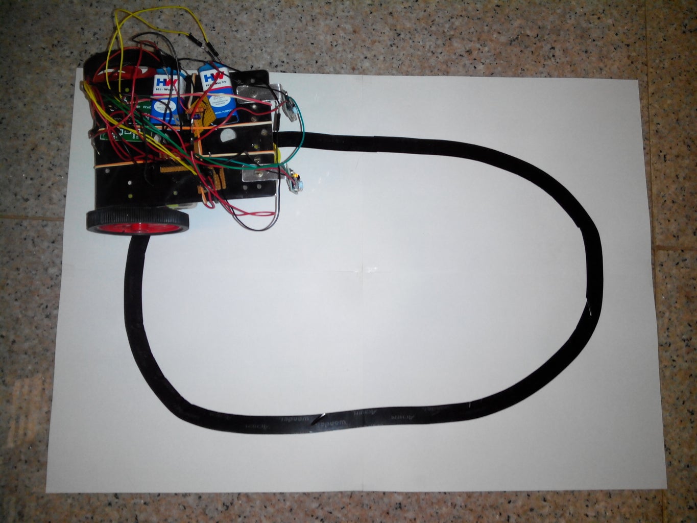
Now to trial run the line follower robot build a test board.
Use a PVC black tape and papers to prep the board.
once it is set power it up and watch the robot follow the line.
Step 11: USES

The line follower robot is a great feat of combining both software and hardware and prototyping.
This is a the most common test for robot hobbyists .
With such a cheap way we can all afford failures and move forward instead of not trying at all.
Breaking all innovative barriers.

Participated in the
Explore Science Contest

Participated in the
Rubber Bands Challenge

Participated in the
On a Budget Contest


