

Introduction: Make Your Own Arduino Testing Board! Made at Techshop!


After many student-day years messing around with Arduino boards, then migrating to PIC microcontrollers, before returning to AVR chips, I found that the latest Arduino bootloader/board options got rid of most of the original limitations that made me look elsewhere.
I don't know about you, but very rarely do I make projects that don't have space constraints. And most Arduino boards are huge! For example, if you are interested in any kind of wearable sensor-related guise, these boards are bulky, widely shaped and downright ugly to look upon!
Not to mention they are expensive.
The other hindrance for me with Arduino before now was that you were seriously limited in how many analog pins you could have in these ready-mades. Nowadays, with a couple of multiplexers, a boot loaded AVR chip and a bit of breadboarding, you can set up an environment with more analog inputs/outputs than you'll probably ever need, all under 10 bucks!
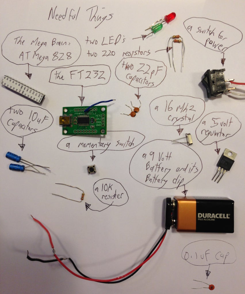
I got the chip from Sparkfun for under 6 bucks. NOTE you must get the AVR chip that has the Arduino boot loader on it. The rest of the components are listed in the image. Aside from these, you will also need a soldering iron, a multimeter and breadboard. See the second pic on how I clipped two wires to the multimeter so it can be used for testing on the breadboard.NOTE: the images I included use extra jumper wires spread around the board so all connections can be seen easily. Normally you wouldn't need them and actually shouldn't, since they can add noise to the whole circuit.
Step 1: Set Up Power Supply


Firstly we need to set up the load and 5 volt power supply powering the whole board.
Firstly, I like to solder two jumper wires to the battery clip, so that I can stick them into the breadboard to check connections.
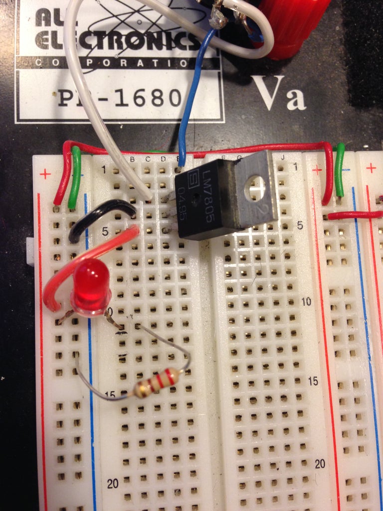
Second, set up the regulator. According to the ATmega's datasheet, it should have a supply of around 5 volts. But our battery is 9 volts. You can use either an 805 voltage regulator, or a low dropout 2940 one, which basically uses less power than the 805. Either one will work.
Pin 1 should go to the raw 9 volts.
Pin 2 is Ground.
Pin 3 -s the 5 volts to supply the whole board.
This is all well and good, but this setup is always on. We will want to set up a switch, so that the board can be turned on and off. Stick a switch in between the +9 volt battery clip and Pin 1 of the Regulator.
Next, lets set up a power LED, so we know if it is turned on or off. LED diodes are polarized, and we all know what will happen is we get the pins mixed up, dont we..... See the images to see how it can be breadboarded.
Next, we need to decouple the supply. Add a 10uF capacitor between Pin 1 of the regulator and the ground as well as a 10uF capacitor between the unregulated 9volt power and ground. Make sure you have the caps heading towards ground, since they are polarized.
Step 2: Add the Micro Controller


Next, add a 10k resister on Pin 1, going to power. This resister prevents the chip from resetting itself accidentally.
Sometimes it is useful to be able to reset the chip, so lets add a momentary switch to our board, going to ground. When the switch is pressed, the chip will be reset. Have one side of the switch on the Arduino's Pin1 and the other side going to ground.
Step 3: Add the External Clock

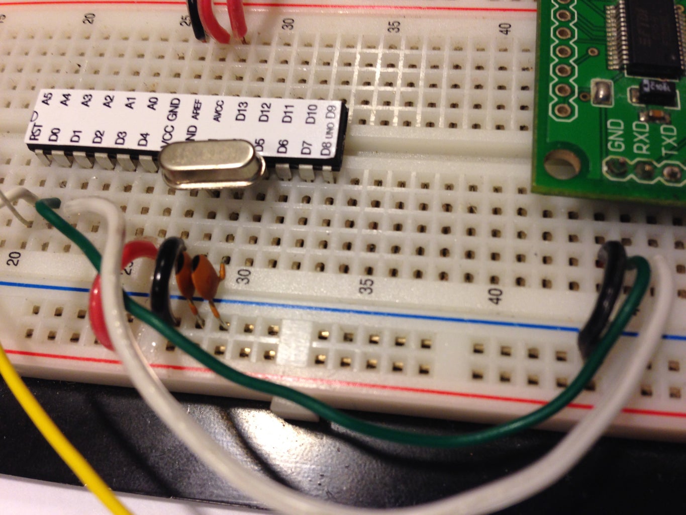
this chip has an 8Mhz internal clock but we will want to override that with a faster external one. Get the 16 MhZ crystal and place it as close to Pins 9 & 10. It is important that the crystal's pins are as close to the chip's pin as possible, to avoid noise messing up the chip's functionality. On these two same pins, add a 0.1uF capacitors going to ground.
Step 4: Adding the FT232
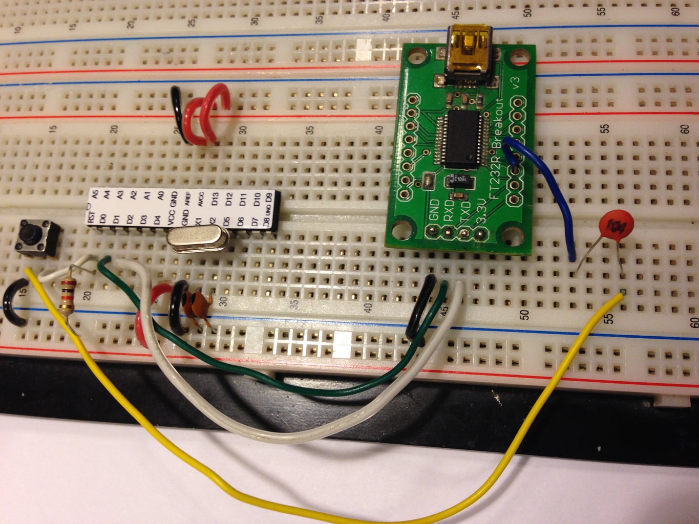

The last step is to addd the FT232 USB module to the board. This is the way we can hook the chip up to a computer to upload/burn programs to it!
The Ground pin needs to go to ground, while the RXD (or receive Data pin) needs to go to the chip's TXD pin (Transmit Data pin). Also, the RT232 TXD pin needs to go to the chip's RXD. This is the way serial communication passes between the chip and the computer used to upload to the chip.
The FT232 has a DTR pin that needs hooking up but the breakout board doesn't have it configurable. Lets solder a jumper lead to its DTR pin, which can be found by flipping the module upside down. have that pin going to Ground via another 0.1uF capacitor.
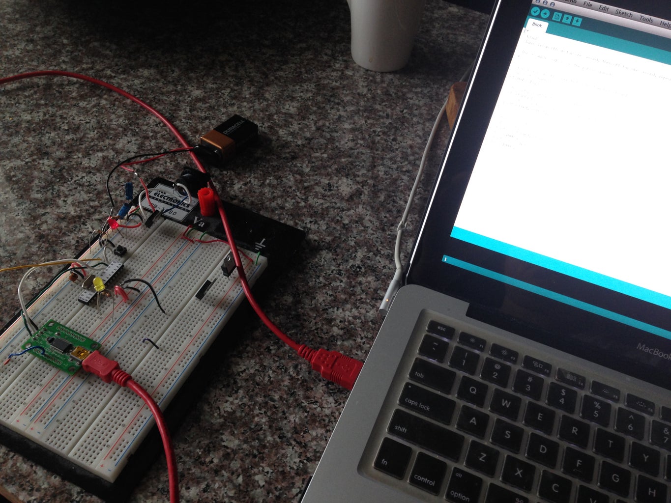
thats it! you are ready to upload your sketches using the Arduino program!


