

Introduction: Making a Semi-Modular Perfboard Arduino


This instructable will outline the steps necessary to create a functional, modular, yet slightly minimal, but reliable, Arduino clone. It is my first instructable, so enjoy!
When I set out to build this Arduino, I didn't plan on making an instructable for anyone else to build one. However, while researching various methods, breadboarding several ones, and soldering a few others, I determined what worked well, and what seemed to have some bugs with the way they operated. Simply put, not all clones are equal. And while I make no claims that my way is the best way, it works well for me, with little to no bugs in the operation.
The requirements I had for this build were the following:
1) A reliable Arduino
2) With enough parts, but keeping it simple
3) With the ability to run at either 8Mhz or 16Mhz, or any other feasable speed.
4) Having enough VCC and GND pins to suit any project
5) Powered from a 12V jack
6) And with a footprint no larger than a Uno.
I also wanted to keep to a DIP28 package, preferably the ATMega8 or ATMega328.
I believe that I have successfully met those requirements with this build. So lets take a look at the components that I used.
Step 1: Choosing Your Parts
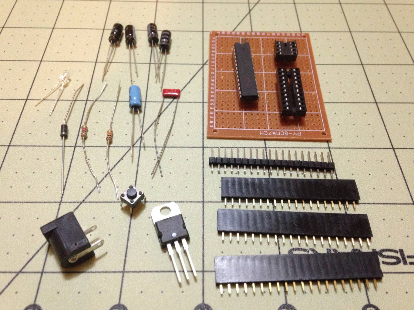
When it comes to electronics, substitutions can in most cases be made. But always remember, it's better to over build than it is to under build. So here are the parts that I used.
1x 12V Jack
1x LM7805 Voltage Regulator
4x 10uF 25V Electrolytic Capacitors
1x 4.7uF 16V Electrolytic Capacitor
1x 0.1uf or 100nF Ceramic Capacitor
1x IN4001 50V 1Amp Diode
1x 10k Ohm 1/4 watt 5% Resistor
1x 1k Ohm 1/4 watt 5% Resistor
1x 3mm Blue LED 1x Tactile Switch
1x 5x7cm perfboard
1x DIP28 socket (I used a DIP20 and a DIP8)
Some male and female pin headers
Small guage wire(Solid or Stranded)
(Optional) Ceramic Resonator rather than a crystal.
"Why so many capacitors?" you might ask. Well, electronics are strange indeed. Laws of Physics are always at work, and this plays a part in how circuits must be constructed in order to work as intended. I am not going to delve into the details, because I'm an amateur. I'll leave that for the people who have a better understanding of this. But, capacitors perform several different functions in a circuit. The two that we are primarily concerned with in this case are decoupling, and filtering.
DC power sources can often superimpose an AC signal, or sine wave, onto the circuit. This is undesirable. A decoupling capacitor can prevent this from happening in the circuit, as well as help provide a stable voltage during any switching that takes place in the circuit (read: voltage drop). A filter simply helps filter out noise that is found within the circuit.
Remember, in most cases substituting components is fine, this presents variables that cannot be addressed in this instructable. If you choose to use different capacitors or resistors, there shouldn't too many issues. But without the foresight to know how your circuit will perform, I can make no guarantees. Having said that, if one were to decide to use two larger capacitors instead of the 4x 10uF electrolytic capacitors, there should not be an issue. I simply used 4x to give myself a overall rating I felt more comfortable with. My understanding,and what you must keep in mind, is that smaller capacitors, essentially, decouple faster. While larger capacitors do a better job at decoupling and stabilizing. So if you decide to make alterations to the parts bill, you should carefully choose what components you will be replacing with.
Step 2: The Schematic, and a Few Notes on Analog

Being a hobbyist with no formal training in electronics, one of the things that I found when it came to schematics on the various websites was they didn't clearly depict, at least to me, where certain components should be placed, read: best practices. Often I found that certain components were wired to a supply symbol, rather than showing how it should be wired for best practices. I.e. Should the capacitor be close to the MCU, or close to another component.
While this may seem obvious to a electrical engineer, it can often be confusing to the amateur with little to no formal training, which includes myself. With this schematic I've attempted to show exactly where I have decided to wire each component, with the exception of the LED and accompanying resistor which may be wired to any source of VCC and GND.
When it comes to the analog side of the microcontroller, I have found that there are five common ways that people on the Internet typically like to wire this side. These are: do nothing with AREF, AREF to AGND, AREF to AVCC, AREF to an external voltage, and lastly using a 0.1uF capacitor as a low pass filter between it and ground. Each type of connection has its advantages and disadvantages. I have chosen the last type of connection for the purpose of this build. The benefits of one type of connection over another is not within the scope of this article. But my understanding is that with using the low pass filter variant the Analog/Digital converter can internally select the appropriate function, except for external voltage, while the filter helps to reduce noise in the analog side of things.
If you decide to go another route, that is your call. My analog pins seem to work fine. But obviously have limitations in the sense that I cannot input an external voltage.
Another consideration, which doesn't bother myself, but may be of interest to the amateur is the diode. I used a IN4001 silicon diode. This particular diode has a 1.5v forward voltage drop (I believe). Meaning that there will be a drop in voltage after the diode. In my build, after the decoupling capacitors on the voltage regulator I get a reading of 4.98v. After the diode the voltage varies between 4.24-4.26v. You can see this is a substantial drop in voltage. And, this may cause problems with certain applications.
One way to increase the voltage back to an acceptable level would be to use a transistor along with a trim-pot to reach a stable voltage in the acceptable range of your application. But considering that there won't be any problems with the function of this board, I have chosen to leave that as an issue best addressed by the builder and his/her needs.
Step 3: Laying Out Your Components

You can see above the way I populated my board. Two components that I want to point out are on either side of the pcb. To the left side, there is a 3x female pin header for inserting a ceramic resonator. And to the right, although hard to see next to the red wire, there is a red 0.1uF ceramic capacitor.
I put a bit of thought into how this board should be populated. I looked at various designs. And came up with a layout that worked well on the size board I planned on using.
On either side of the MCU you will see three sets of headers. These are not duplicates. Moving from the inside out: MCU Pin, GND, VCC. In other words, I have provided a GND and a VCC connection for each pin on the board.
Feel free to work out something different if it works better for you.
Step 4: The Bottom Side of the Board, Traces, and Soldering...
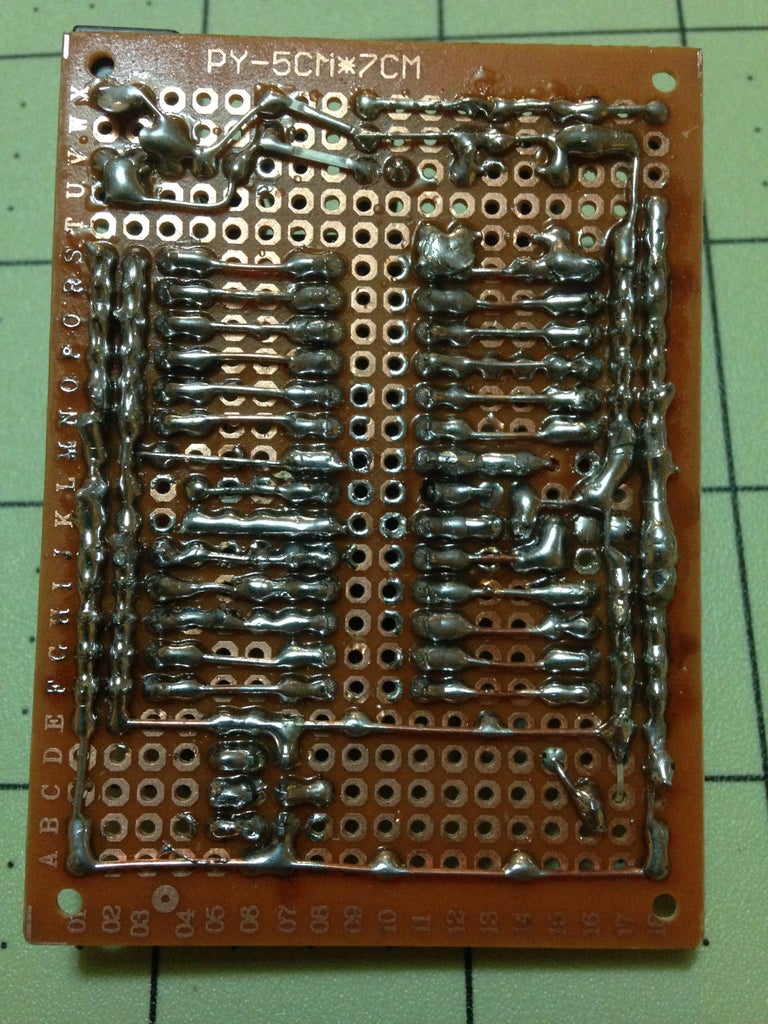
You can see the bottom of the board in the supplied picture. It has very little unused space due to using long traces. I wanted enough room on either side of the MCU to work. This gives the board a workable size. Hopefully this picture will be detailed enough to let you lay out your own with very little confusion.
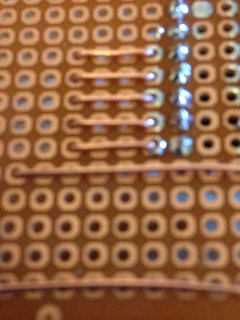
For the traces, I like to first solder in the components at their respective locations, and then bend the excess to the next connection. However, sometimes this is impossible. Take for example the DIP socket and the female headers. There isn't anything extra to bend. Some people use small wires, some glob solder from one pin to the next across multiple holes. Personally I found wires create to much of a mess, and solder globs just don't work well past one or two holes. So I use a different method. I strip some solid core wire, cut and bend a piece so that it will fit in the holes next to the pin to be soldered. Once done, I then solder the makeshift leads in place, then come back over them connecting to the appropriate pins. A picture has been provided.
Step 5: Cleaning Off the Flux

This is the difficult part...
I use Rosin Core 60/40 solder. As it turns out, the rosin is hard to remove. I use alcohol and a toothbrush to clean it up, but honestly, it mostly just spreads it around in an even layer. Once it dries I haven't had any problem with the excess rosin., However my perfboard does turn a darker brown, giving it a vintage look.
If you use acid core, or another flux, there are plenty of ways to clean your pcb, but do clean, acid can corrode your work over time.
Step 6: Options


There are several options that you can choose to do at this point.
Something I added to my board, but isn't necessary, as you can use the female headers with an adapter, is to wire in a ISP header. You can see in the layout section how simple this is. I didn't use any resistors... But I will say this, in my experience a diode is absolutely necessary on VCC after the voltage regulator in order for a programmer to work. I have always gotten some type of interference from the Regulator when I haven't used one.
You could put some type of protective layer on the bottom side of the board. I have used liquid tape in several heavy layers. But you have to go thin the first few times, as it will flow through any unsoldered holes on the pcb. But once done, leaves a nice rubbery coating on the bottom of your board.
Another option is to use a resonator to get 16Mhz from the microcontroller. When doing this I found that it is necessary to coat the legs with a little solder that way they better fit the Female Headers. It doesn't take much, and really helps ensure you have a solid connection.
Step 7: Testing Your Board
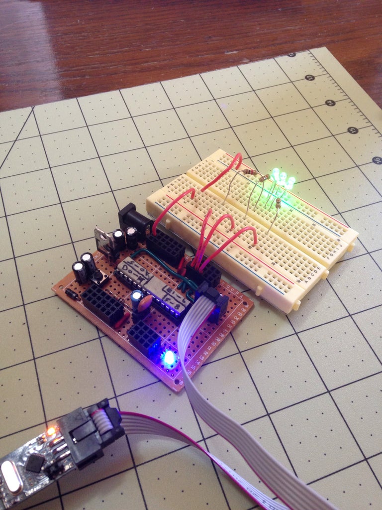
The next step is to upload a sketch and test your board. If you have followed my instructable and used the schematic and layout I provided I all but assure you that it worked. As you can see in the video, mine works.
