Introduction: Microcontrollers 101 - Useful Beginner Circuits and Saving Hardware on Your Projects
Usually when you start working with microcontrollers or other development boards for the first time, you constantly check on the internet how to connect things on the pins or maybe you are following a tutorial. And is also a big chance that you may be using pre-built modules with sensors, power interfaces and other kinds of stuff around there.
But what happens when you want to develop your own circuits? Or maybe obtain more professional and cost effective designs? You will need to build everything from scratch, so this way you completely understand how your device works and you can also built your own professional looking project.
In this guide I will show you some of the most basic and common circuits you can attach to your microcontroller to interact with the physical world. But also some tips and tricks that would allow you save components, connections and resources in your microcontroller project.
This guide of course apply to most of the microcontrollers and development boards around there. Like AVR's, PIC's, Arduino's, Raspberry's and much more.
We will be using an Arduino UNO, a breadboard and some components to our demos in Tinkercad Circuits.
Let's get started!
Step 1: Input From a Button
When you want to use a button in your project, your micro will need to read some voltage on the pin. Leaving a pin floating can cause a lot of problems and fake triggerings. This is why we use a pull-up or pull-down resistors, they are common resistors around 10k ohms that goes between voltage and your micro pin. They help define a logic state when the button is not pressed but also will no make a short circuit when you press it.
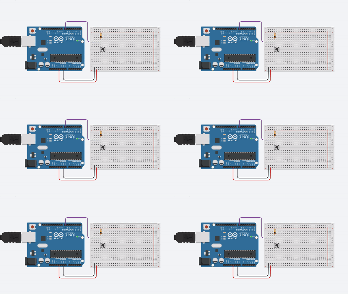
In this case we are using a pull-up resistor that goes to 5v and the other side to the button, the button goes to ground and the other side to the resistor and the micro input pin. As show in the image, this will send GND when the button is pressed and 5v when is not.
We are using the following code in our Arduino:
void setup(){
  pinMode(7, INPUT); //this is the input pin
  pinMode(13, OUTPUT); //this is the built in LED
}

void loop(){
  if(digitalRead(7) == 0) //when we read a logic LOW
  {
     digitalWrite(13, HIGH); //turn on the LED
  }
  else //when the button is not pressed
  {
     digitalWrite(13, LOW); //turn off the LED
  }
}
And here is it in action, when we press the button the led turns on. Otherwise it stays off.
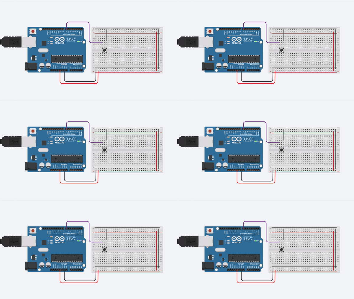
And as I have told you earlier of course we can save a component here, it is the resistor. Most microcontrollers have internal pull-ups resistor, we just need to enable it like this on the code:
void setup(){
  pinMode(7, INPUT_PULLUP); //this is the input pin with internal pull-up
  pinMode(13, OUTPUT); //this is the built in LED
}

void loop(){
  if(digitalRead(7) == 0) //when we read a logic LOW
  {
     digitalWrite(13, HIGH); //turn on the LED
  }
  else //when the button is not pressed
  {
     digitalWrite(13, LOW); //turn off the LED
  }
}
Your circuit will work well with short wires using the internal pull-up, but consider using the external pull-up if you are planning to use longer wires or are you having troubles with fake triggers.
Is really that easy! But when happens when you want to connect a lot of button to your micro?
Of course you will need one pin per button, if you have a lot of buttons that's a problem. Fortunately there are methods to plug a lot of buttons using less pins. I will show you the most popular in the next section.
Step 2: Multiple Buttons With Less Pins
There are 2 main techniques for reducing pin use when connecting buttons. One is multiplexing and the other one is using the Analog to Digital Converter. We are going to discuss the second one.
When using the micro ADC we can plug a lot of button using only a single analog pin!!! This is done thanks to the Voltage Divider Rule, each button has a resistor from a different value and when pressed they will send a different voltage level for each one. With this method you can only read one button at a time. Pressing multiple buttons at same time will not work properly, useful for some applications but not the right solution for others.
It will work like this, pay attention to the voltmeter on the top when I press each button:
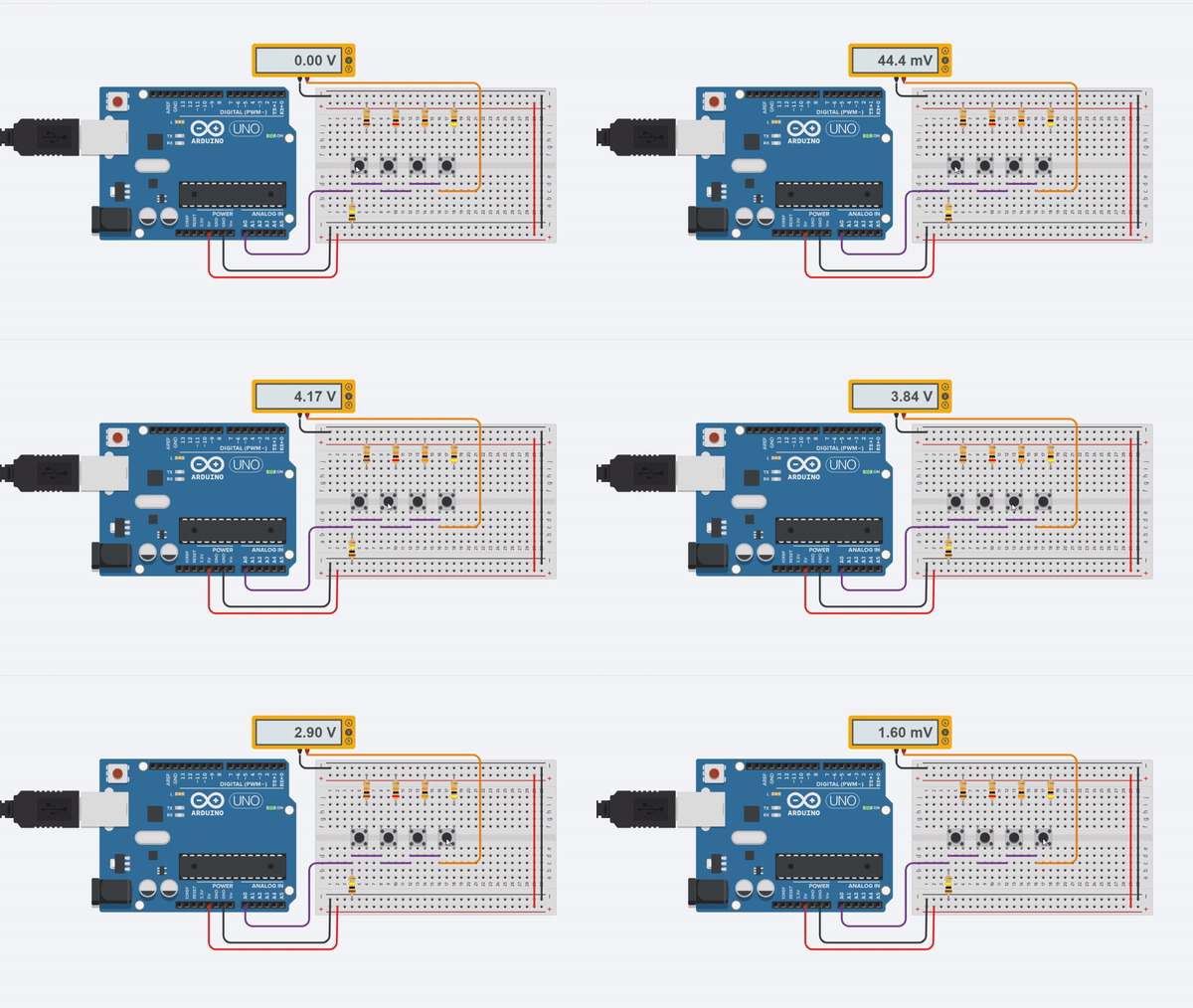
As you can see the buttons give us the following voltages:
- Button 1 = 4.54v
- Button 2 = 4.17v
- Button 3 = 3.84v
- Button 4 = 3.57v
On a micro this values can be easily obtained and them classified with some code similar to this:
float voltage =  analogRead(A0) * (5.0 / 1023.0);

if(voltage >= 4.44 && voltage <= 4.64) //remember to leave some tolerance in your values
{
  //do something
}
Now let's talk about the other method, multiplexing. When multiplexing you need to have 2 kinds of pins, inputs and outputs. In this case I will use outputs for columns and inputs for rows. We basically need to send 5v to the columns each one at a time, so one will have 5v and the other ones gnd. Them we use inputs to read this voltage on the rows, if we have 5v on one of the inputs a button is pressed. Now we only check what column is active and we will now the button coordinates on the matrix. Sounds complicated, but actually super easy.
In the next example we have 6 buttons connected using only 5 microcontroller pins! The benefits of this method came when using much more buttons, like in a keyboard. But for this demonstration it will be fine, the led will blink multiple times depending what button is pressed. Check it out:
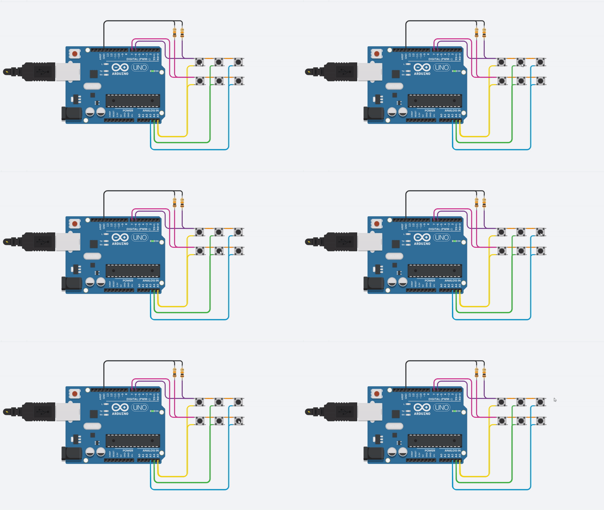
And the code is the following one:
void setup(){
  pinMode(7, INPUT);
  pinMode(6, INPUT);
  pinMode(13, OUTPUT); //this is the built in LED
  pinMode(A3, OUTPUT);
  pinMode(A4, OUTPUT);
  pinMode(A5, OUTPUT);
}

void loop(){
  digitalWrite(A3,LOW);
  digitalWrite(A4,LOW);
  digitalWrite(A5,HIGH);
  if(digitalRead(6) == 1) //when we read a logic HIGH
  {    blink(1);   }
  if(digitalRead(7) == 1) //when we read a logic HIGH
  {    blink(2);   }
  digitalWrite(A3,LOW);
  digitalWrite(A4,HIGH);
  digitalWrite(A5,LOW);
  if(digitalRead(6) == 1) //when we read a logic HIGH
  {    blink(3);  }
  if(digitalRead(7) == 1) //when we read a logic HIGH
  {    blink(4);   }
  digitalWrite(A3,HIGH);
  digitalWrite(A4,LOW);
  digitalWrite(A5,LOW);
  if(digitalRead(6) == 1) //when we read a logic HIGH
  {    blink(5);   }
  if(digitalRead(7) == 1) //when we read a logic HIGH
  {    blink(6);  }
}

void blink(int times){
for(int x = 0; x<times;x++)
{
digitalWrite(13,HIGH);
delay(500);
digitalWrite(13,LOW);
delay(500);
}
}
Now let's talk about controlling external led's.
Step 3: Controlling LED's
Now we will talk about outputs, but more precisely about controlling led's with a microcontroller. The most common circuit is the following one, just one led blinking connected directly to an output pin with a 330 ohm resistor.
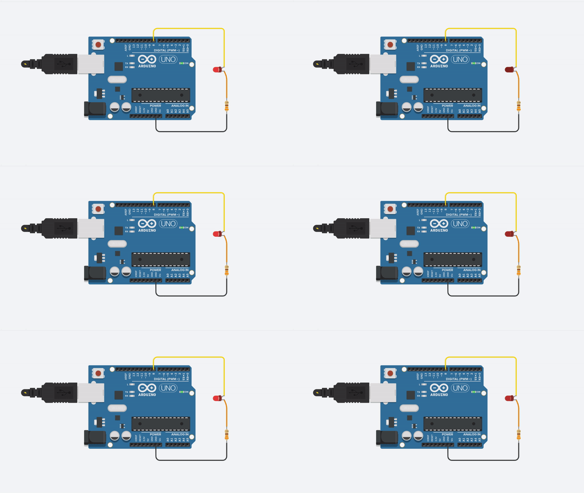
And the code is the following:
void setup(){
  pinMode(8, OUTPUT);
}

void loop()
{
    digitalWrite(8,HIGH);
    delay(500);
    digitalWrite(8,LOW);
    delay(500);
}
That's easy, let's get a little bit more complicated. I will show how to control 2 led's with only one output pin on a microcontroller. Check the following circuit:
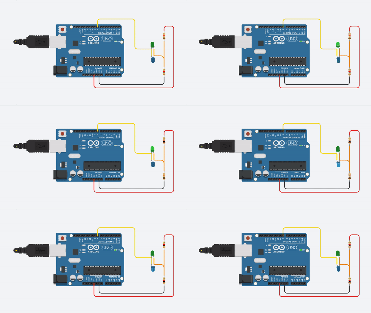
As you can see we have created a 2.5v supply using a voltage divider, when we put a logic high on a micro pin we turn on 1 led with the voltage difference and when we put a logic low we create another voltage difference but now is opposite to the first one turning the other led. And if we don't set voltage (pin as an input) we turn off both led. To turn on both led's we only need to toggle the pin from high to low more than 30 times per second and the persistence of vision effect will make appear to the human eye than both led's are turned on at the same time.
The code to do that looks like this:
void loop(){
    pinMode(8, OUTPUT);
    digitalWrite(8,LOW);
    delay(1000);
    digitalWrite(8,HIGH);
    delay(1000);
    pinMode(8, INPUT);
    delay(1000);
}
Also you can multiplex the led's as we do with the buttons, but now all pins are outputs for rows and columns. We now have a LED matrix:
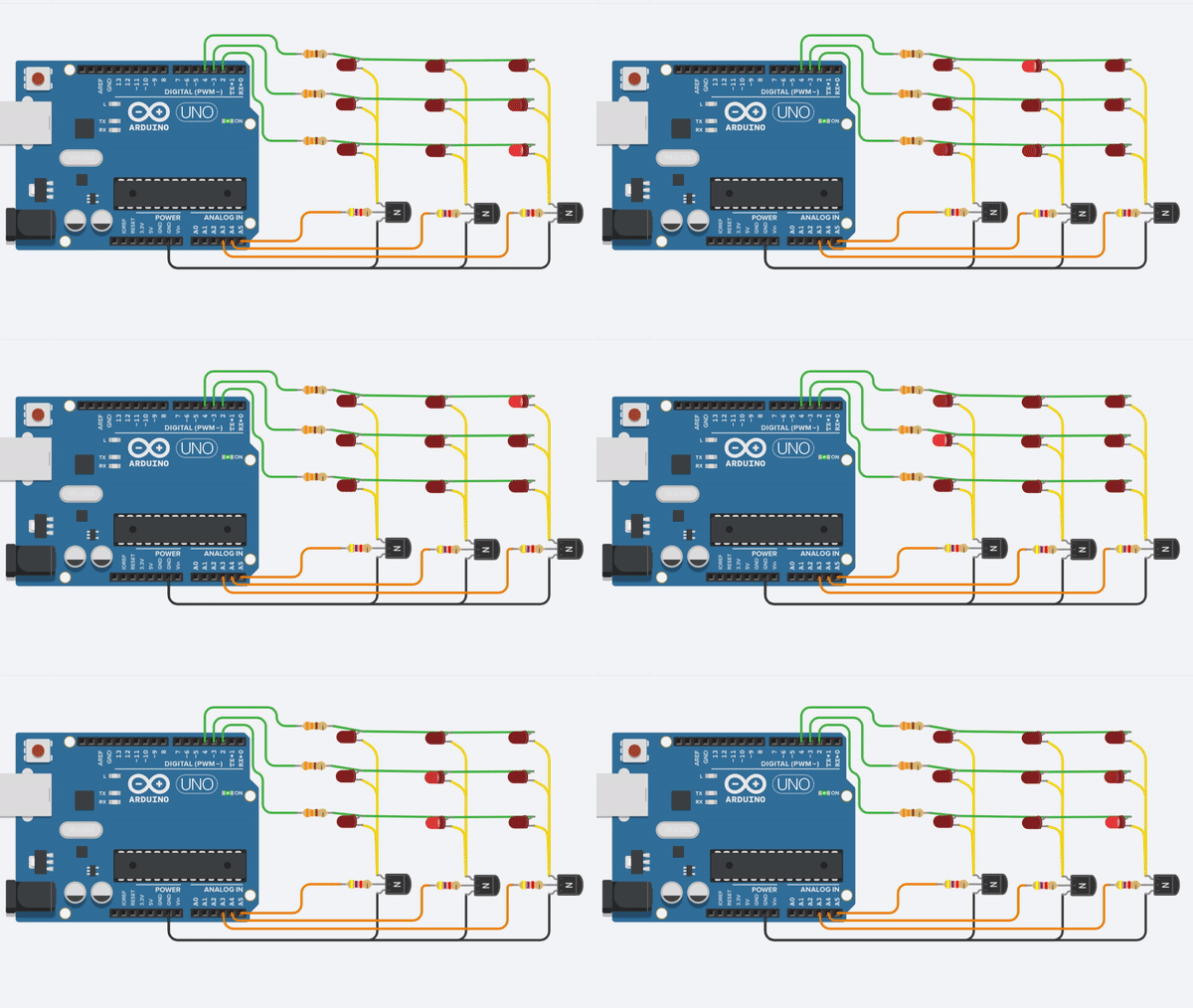
This is the same way some led displays work, you can get the code below:
void setup(){
   pinMode(4, OUTPUT);
   pinMode(3, OUTPUT);
   pinMode(2, OUTPUT);
   pinMode(A3, OUTPUT);
   pinMode(A4, OUTPUT);
   pinMode(A5, OUTPUT);

}

void loop()
{
for(int x = 1; x<=3;x++)
{
  selectColumn(x);
  for(int y = 1; y<=3;y++)
  {
    selectRow(y);
    delay(500);
  }
}
}

void selectColumn(int column)
{
  switch (column) {
  case 1:
  digitalWrite(A5,HIGH);
  digitalWrite(A4,LOW);
  digitalWrite(A3,LOW);
  break;
  case 2:
  digitalWrite(A5,LOW);
  digitalWrite(A4,HIGH);
  digitalWrite(A3,LOW);
  break;
  case 3:
  digitalWrite(A5,LOW);
  digitalWrite(A4,LOW);
  digitalWrite(A3,HIGH);
  break;
  }
}

void selectRow(int row)
{
  switch (row) {
  case 1:
  digitalWrite(4,HIGH);
  digitalWrite(3,LOW);
  digitalWrite(2,LOW);
  break;
  case 2:
  digitalWrite(4,LOW);
  digitalWrite(3,HIGH);
  digitalWrite(2,LOW);
  break;
  case 3:
  digitalWrite(4,LOW);
  digitalWrite(3,LOW);
  digitalWrite(2,HIGH);
  break;
  }
}
Now let's talk about power interfaces.
Step 4: Power Interfaces
One of the most common power interface is a transistor, usually microcontrollers can supply only a few milliamps. But with a little bit of help from a transistor we can control power hungry devices like a DC motor or relays. A relay can also be useful for powering AC loads. Here is an example of a relay circuit using a transistor to power the relay, otherwise you will burn the microcontroller pin.

With this same circuit you can control a DC motor in a single direction, but you will be able to control speed using PWM:
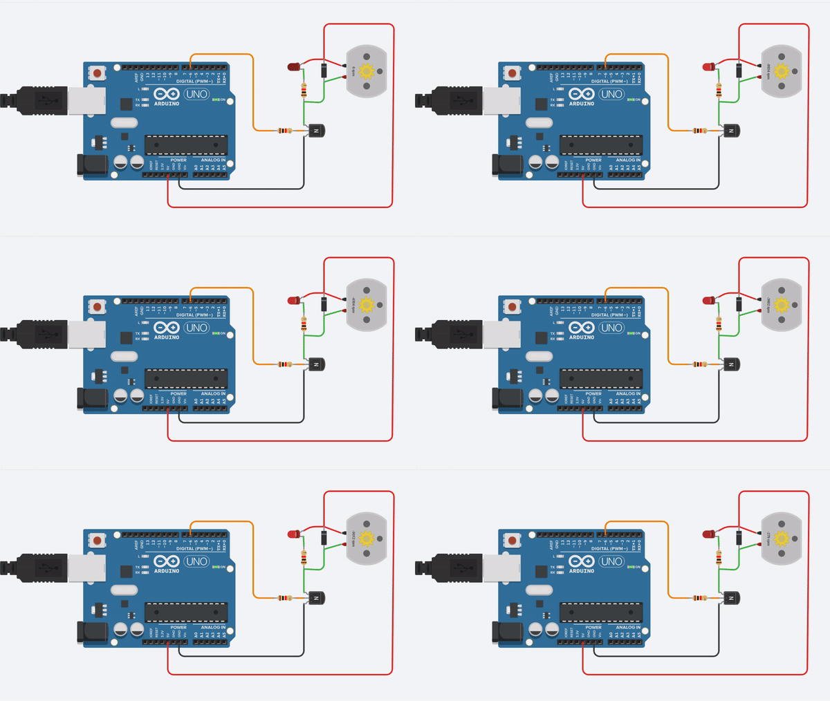
And here is the code for this last example:
void setup(){
  pinMode(6, OUTPUT);
}

void loop()
{
  for (int x = 0;x<256;x++)
  {
    analogWrite(6,x);
    delay(5);
   }
  for (int x = 255;x>0;x--)
  {
    analogWrite(6,x);
    delay(5);
  }
}
As you can see this are some simple but useful things that I have learned over the years and I think they may be useful for someone that is starting. Mixing things together would allow you to get some complicate projects quickly.
One of my favorite advices is the following: "Don't try to eat the whole pizza on one bite, do it one slice at a time." When developing a project do it by sections and make it work properly before moving to another section, at the end mix all together to obtain a fully functional project. If you try to do it at the same time you will end making a mess and without any idea what is wrong or why it not works.
Step 5: Final Hack
Last but not least, here is my final circuit for saving hardware when using a microcontroller. Usually microcontroller works at 5v or 3.3v, but sometimes you will need to read a signal with a greater voltage. People has come with complicated solutions like using an optocoupler, a resistor divider or even an op-amp.
But most people don't know that this can be archive easier than that, most microcontrollers have zener diodes on their inputs to get rid of overvoltages. But this diodes only can handle a little amount of current. Just limit the current using a simple resistor and you are ready to rock without complications:
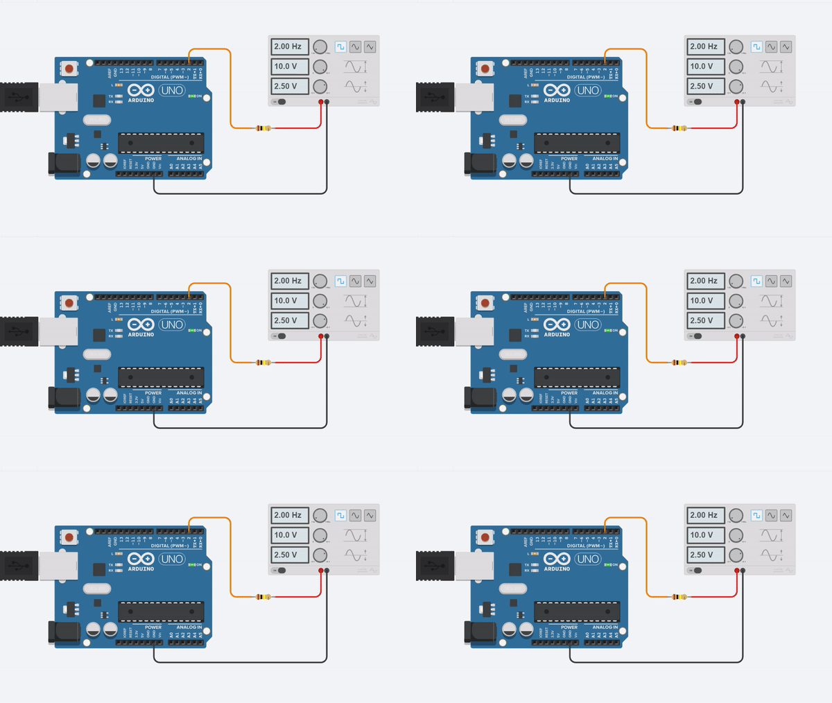
Just check the datasheet to know if the pins have the diodes and also the amount of current they can handle.
I hope you enjoy this tips, if you know another one leave it on the comments.
Thanks for reading :)

Participated in the
Electronics Tips & Tricks Challenge


