

Introduction: Motion Sensitive LCD Real-Time Clock/Alarm/Timer (Updated Program)


I needed a clock for my home office (where I spend weekend mornings building robots and such) and I wanted it to fit in with the decor of my electronics work bench. I decided to build one with all the "guts" exposed. The specs were:
- Real Time Clock
- LCD Display Date and Time
- Include Minute Timer (for timing things while building projects)
- Include Alarm (to remind me I've been in here too long)
- Motion Sensitive (save power by turning off LCD when I'm not in the room)
- Look Cool on my work bench!
Step 1: Materials


- Arduino Uno (from Radio Shack)
- LCD Keypad Shield for Arduino (from DFRobot)
- DS1307 Real Time Clock (from Adafruit)
- Enclosure Box (from Radio Shack)
- Piezo Buzzer (from Radio Shack)
- PIR (Passive Infra-Red) Motion Sensor (from Parallax)
- Female/Female Jumper Wires (from Adafruit)
- 2.1mm DC barrel jack (from Adafruit)
- 9V battery clip with 5.5mm/2.1mm plug (from Adafruit)
- 9V wall wart
Step 2: Assemble RTC Board


The Adafruit DS1307 Real Time Clock breakout board kit is just that; a kit. All components are included and it's very simple to assemble with a little bit of light soldering. Adafruit provides complete instructions at http://www.ladyada.net/learn/breakoutplus/ds1307rtc.html. The kit even includes a 3 volt lithium coin cell that will keep the clock running for years.
NOTE: Photos are from Adafruit's instruction document.
Step 3: Power Connector


I wanted to be able to remove the Arduino board easily for future tinkering, so I cut the battery connector off of the 2.1mm plug and soldered the wires to the barrel jack. Then, I drilled a hole in the enclosure box and super glued the jack to the box. Now I can easily connect and disconnect the Arduino as needed.
The 9v wall wart simply plugs into the back of the box.
NOTE: If you look closely at the photo, you'll see that I drilled an "extra" hole too close to the screw post and then covered it with black electrical tape when I figured out the jack wouldn't fit there.
Step 4: Attach Cables to All Components

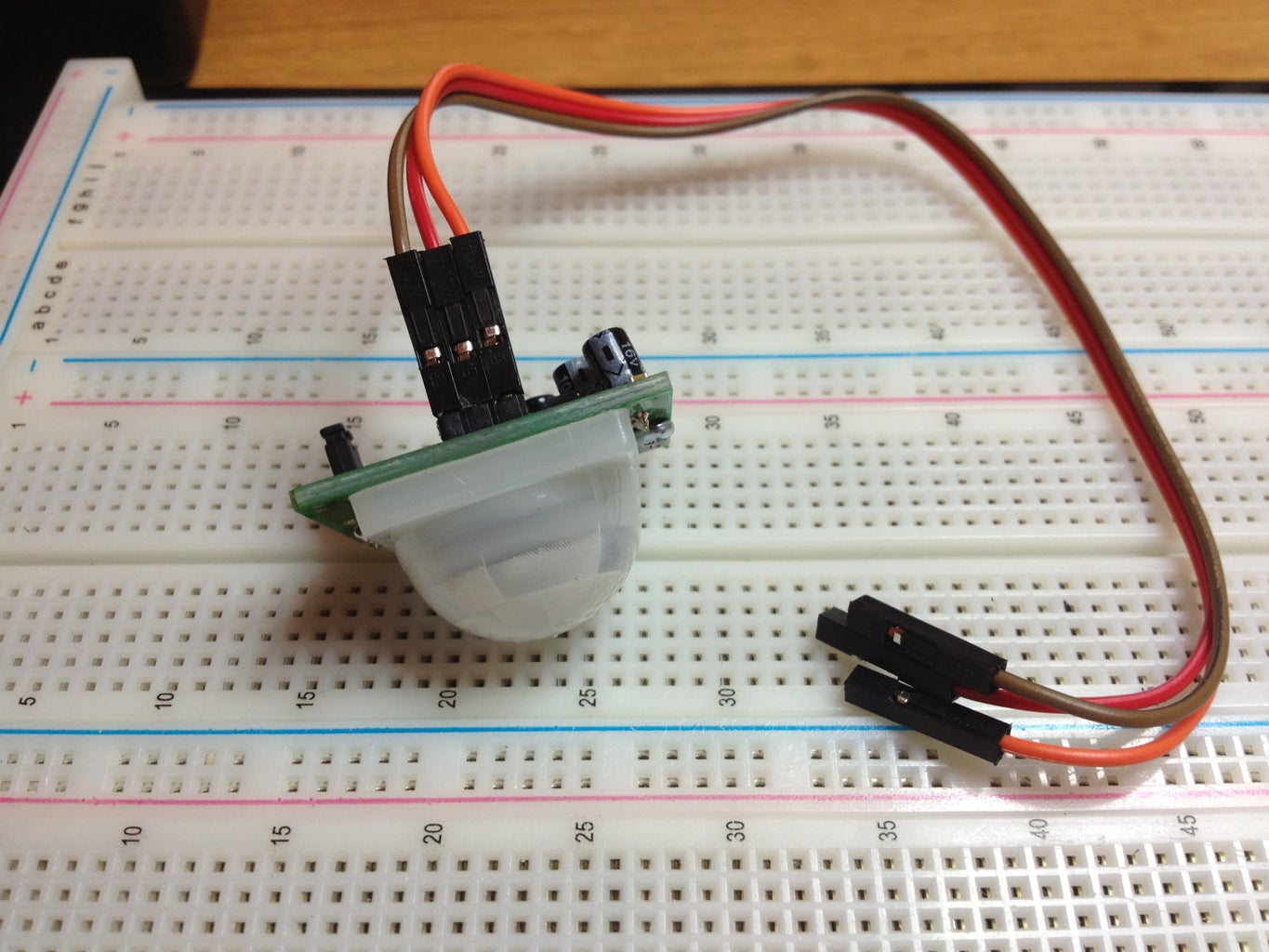


Adafruit sells these really cool Female/Female Jumper Wires in a ribbon cable. I use them for everything I build these days. You just tear off the number of wires you need and they make a nice little pluggable cable for each device.
I attached cables to the RTC, the PIR sensor, and the Piezo buzzer so I can easily connect them to the LCD shield.
Step 5: Connect Everything to the LCD Shield
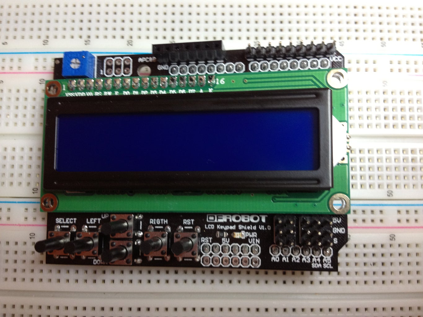
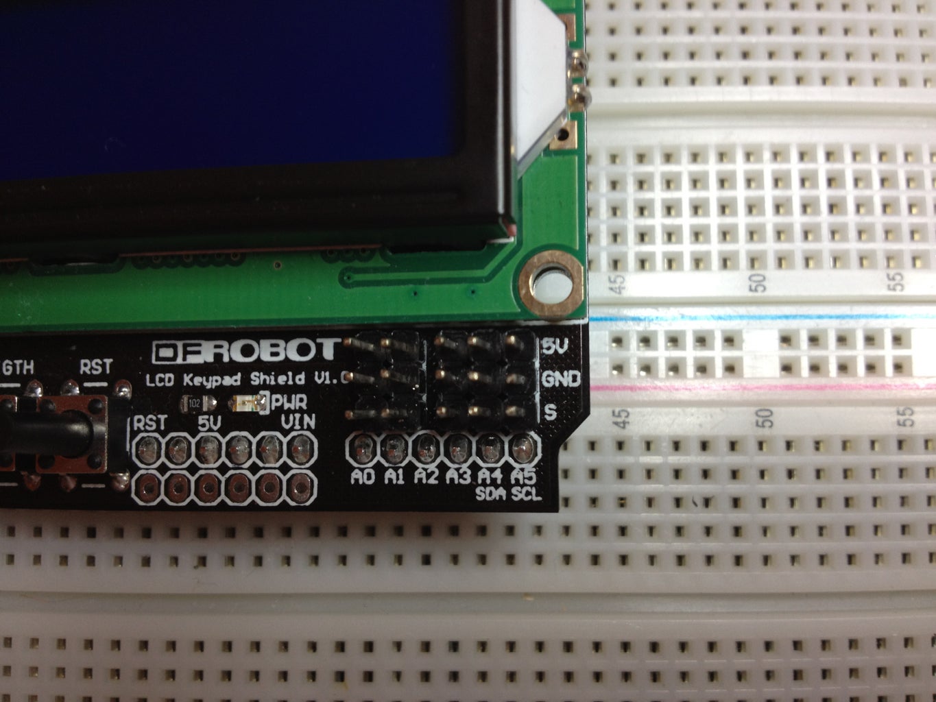
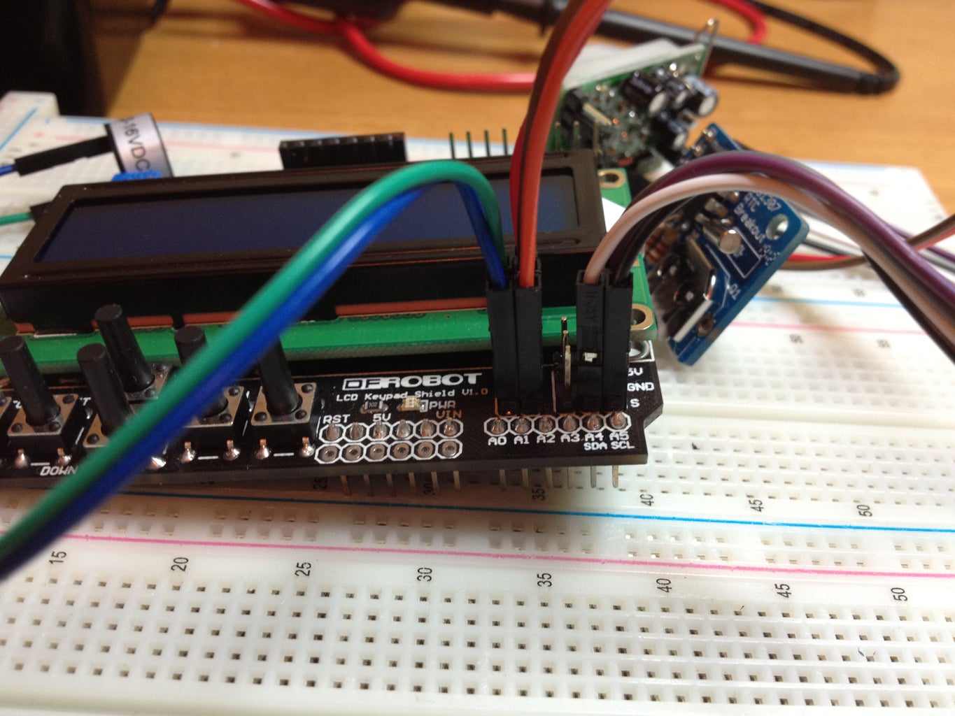
The LCD shield has 5 rows of pins corresponding to analog pins 1-5 of the Arduio board. There's a row for 5v, GND, and signal, so I used these pins to connect the other end of my component cables. I use the analog pins to interface with the RTC, sensor, and buzzer and of course the sensor and RTC need power and ground connections.
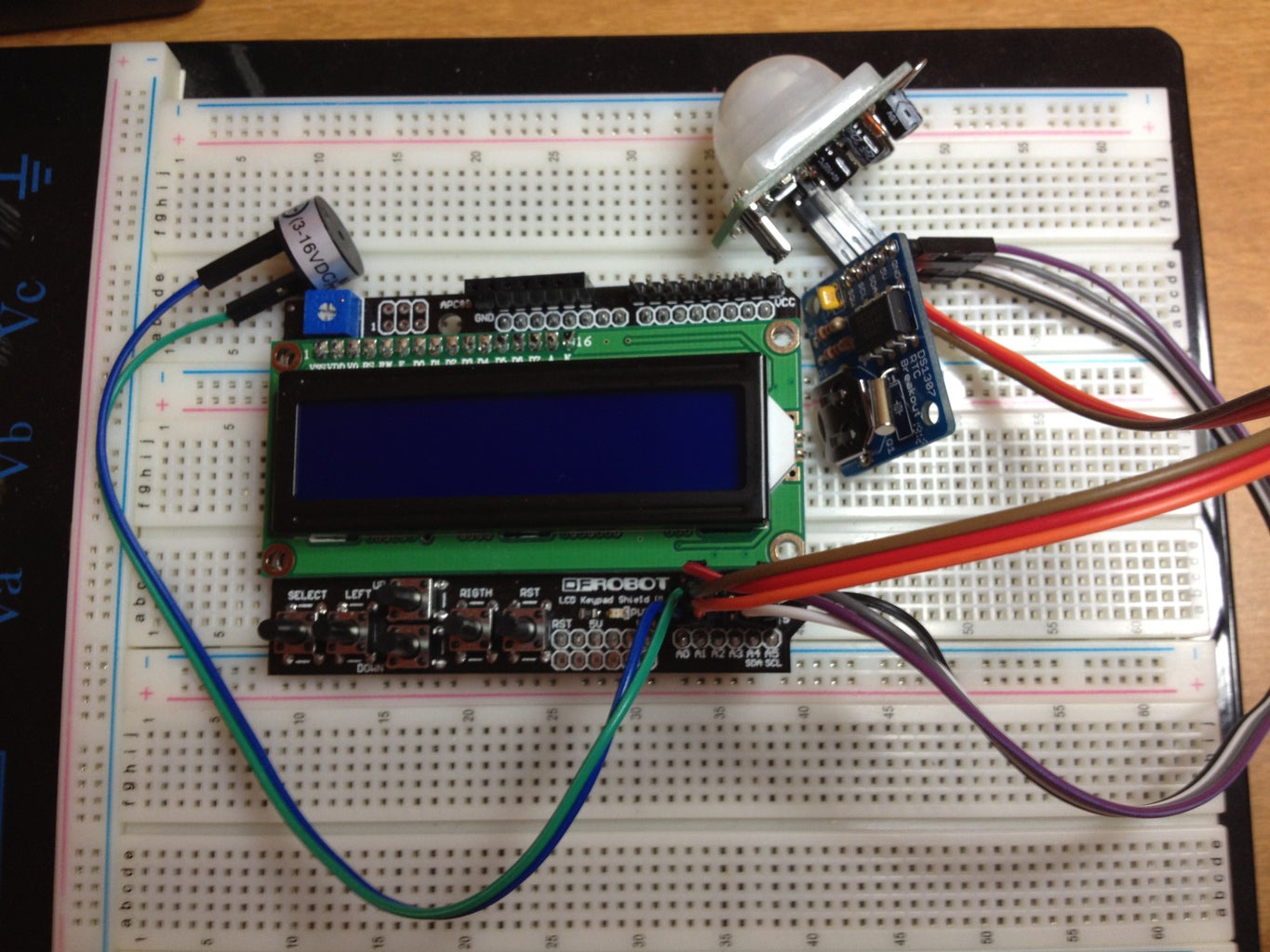
Step 6: Mount Everything in the Enclosure Box
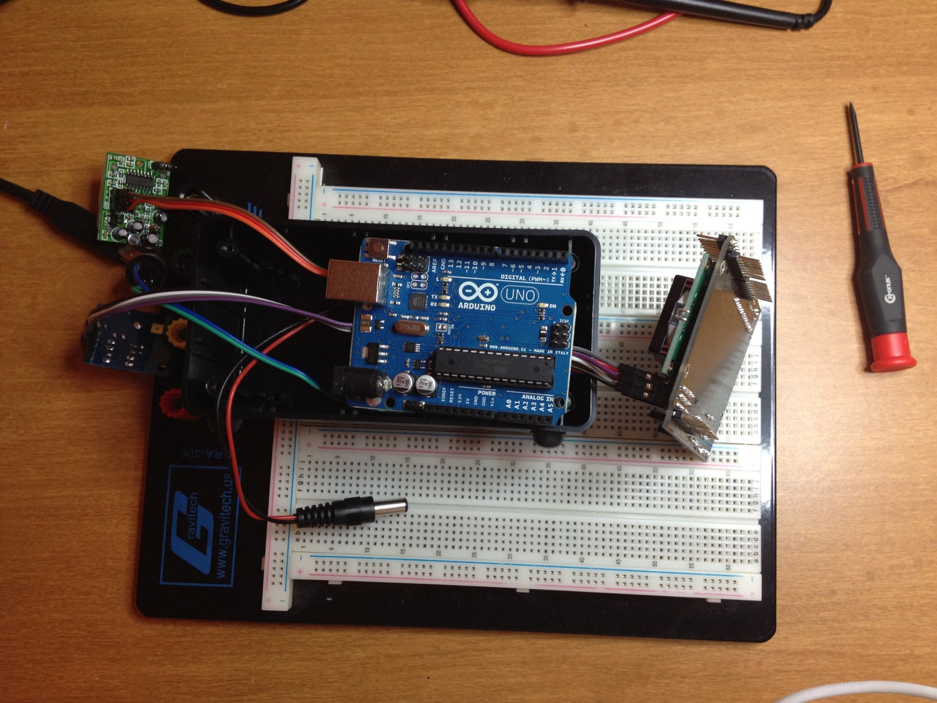


The next step is to attach the Arduino board to the enclosure. I had to lay the cables into the box first and hang the LCD shield to the right while I attached it. Otherwise I would have had to thread the cables through after the fact.
I attached the Arduino to the bottom right screw post on the box. It fit securely with just one screw because the board is exactly the same height as the inside of the box and it rests against the plastic rails inside the box (top and bottom).
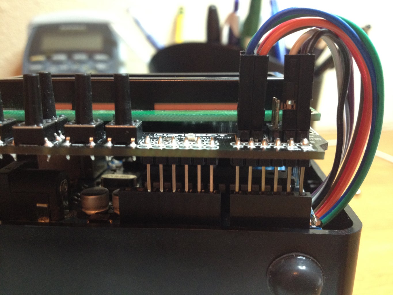
Next, I plugged the LCD shield on top of the Arduino and routed the wires around the right side of the boards.
The RTC board fit nicely in the bottom left corner of the box. I attached it with one screw as well. After attaching it, I was able to plug the power plug into the 2.1mm jack of the Arduino.
I had to mount the PIR sensor so that it could be easily removed since it blocks the Arduino's USB port. So I attached it using a strong piece of wire and looped it around screws on the PIR sensor board and the upper left corner of the LCD shield.
Step 7: Programming the Clock (Updated 7/30/2012)


As I mentioned in the intro, I wanted it to display the date and time, but also have functions for a minute timer and alarm.
The LCD shield has 5 programmable buttons on the front, so I used them to set the different features of the clock. The piezo buzzer creates a beep on each button push and a series of beeps for other functions like the alarm.
Programming the Arduino Sketch
I started with Adafruit's Arduino sketch for the RTC and their RTClib, which is actually a fork of Jeelab's fantastic RTC library. You can find the code at https://github.com/adafruit/RTClib.
Then I added some code from DFRobot for the LCD shield (including the button controls) available at http://www.dfrobot.com/index.php?route=product/product&filter_name=lcd%20shield&product_id=51
And, finally, I added my own code to complete the project. The completed sketch is available on github at https://github.com/mikesoniat/MotionClock.git.
The photos show the LCD as I set the different options.
UPDATED: 7/30/2012
- Fixed noon showing as 12am
- Fixed displaying PMM when switching to PM
- Added alarm set indicator (asterisk after time)
- Validate alarm hours > 0 and < 13
- Fixed allow alarm minutes to be 0 (i.e. 8:00)
- Added setDateTime feature
- Added clearAlarm feature
UPDATED: 8/1/2012 Download Updated Source Code
- Fixed default day and hour settings on set date/time
- Added maxCount to getTimerMinutes
- Fixed alarm set PM
Step 8: Function Buttons
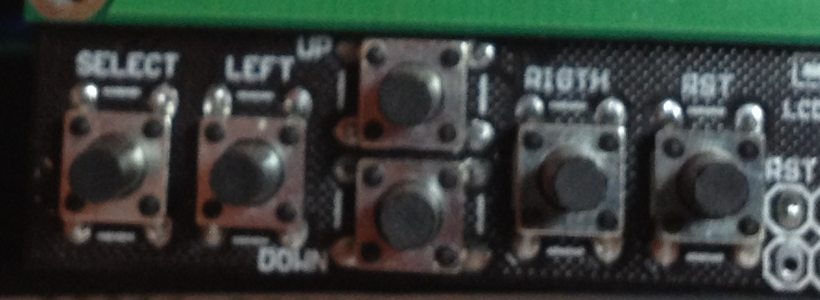
The LCD Shield contains six labeled buttons (see the photo). I programmed the first five as follows:
Button #1 (labeled SELECT) is my Menu button. This button displays a scrolling list of available functions (Minute Timer, Set Alarm)
Button #2 (labeled LEFT) is my Select button. Click to select the displayed menu option. NOTE: Also used to increment by 10s when entering hours, minutes, etc.
Button #3 & 4 (labeled UP& DOWN) are my Increment & Decrement buttons. Click these to increment or decrement hours and minutes while setting the timer or alarm. Also used to toggle AM and PM.
Button #5 (labeled RIGHT) is my GO button. Click to accept the value entered (such as minutes and hours).
Button #6 (labeled RST) is the Reset button which reboots the Arduino


