

Introduction: Multiple LEDs & Breadboards With Arduino in Tinkercad


You can follow along virtually using Tinkercad Circuits. You can even view this lesson from within Tinkercad if you like! Explore the sample circuit and build your own right next to it! Explore the sample circuit in the workplane, and build your own along side it. Tinkercad Circuits is a free browser-based program that lets you build and simulate circuits. It's perfect for learning, teaching, and prototyping.
Find this circuit on Tinkercad
If you want to follow along with your physical Arduino Uno (or compatible) board, you'll also need a USB cable and a computer with the free Arduino software (or plugin for the web editor) installed, plus your Arduino Uno board, solderless breadboard, some LEDs, resistors (any value from 100-1K ohms will do), and breadboard wires.
Step 1: Build the Circuit
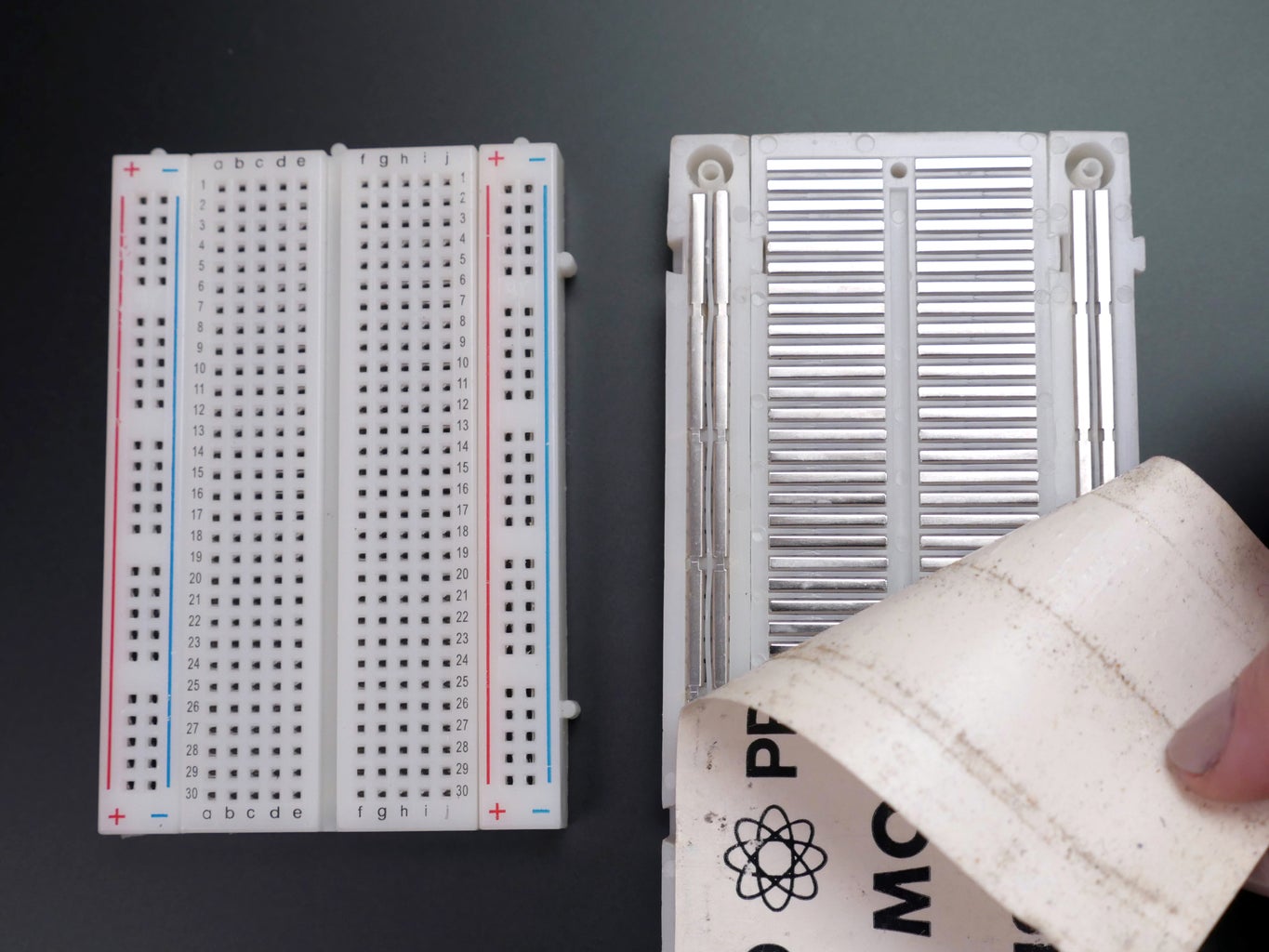
The rows of a solderless breadboard are connected inside, allowing you to connect components by plugging them into the same row as each other. Hover your cursor over points in the virtual breadboard to highlight their connections. The special long rails along the edges are for easy access to power and ground. It’s a best practice to always connect 5V and ground to these long rails as a starting point for any Arduino circuit.

The free-wired circuit pictured in this step is electrically equivalent to the breadboard sample circuit. You can build either way in the editor, but if you are also building a circuit with physical components, the breadboard will help your virtual circuit look the same. Don’t worry if it takes some time to get the hang of using a breadboard!
In the Tinkercad Circuits components panel, drag components to add to your workplane to recreate the circuit shown.
Create wires connecting Arduino's 5V pin with the red (+) power rail on your breadboard, and likewise GND with the black (-) ground rail.
To change your wire colors, select the color in the inspector, or use the number keys on your keyboard to quickly switch between colors. Wire connections to 5V are typically red, and those connected to ground are black.
Position your LEDs so the legs go to two different rows of the breadboard.
Attach wires to any of the holes in the same row to make an electrical connection. Just like before, we want to connect the LED and resistor in series to pin 13 and ground.
Add a few more LEDs to this circuit, along with their companion resistors. For each, connect one end to ground and the other to a different digital input pin on the Arduino board, and customize the wire color.
Double click along the wires to create bends and move them to tidy up your circuit.
Hint: Although you may be tempted to consolidate and use a single resistor for all three LEDs, don't! Each LED needs its own resistor since they don't draw exactly the same amount of current as each other.
Extra credit: you can learn more about LEDs in the free Instructables LEDs and Lighting class.
Step 2: Code With Blocks

In Tinkercad Circuits, it's easy to use code blocks to create an animation effect. Click the "Code" button to open the code editor.
Click on the variable category in the code editor.
To make the speed of the animation adjustable, create a variable that will serve as the amount of time between state changes. Name the variable "animationSpeed”.
At the beginning of the program, set the variable to your desired time, in milliseconds.
Drag the new variable animationSpeed onto the wait block to set the wait time to whatever animationSpeed is set to. Don't forget to adjust the dropdown menu from "seconds" to "milliseconds."
Use another output block to set the next pin 12 HIGH, then LOW, with another pause after each.
Right click and select Duplicate to create a new copy of the block for as many LEDs as you have left, then change the pin numbers to correspond to the connected LEDs. Test out your code by starting the simulator.
Step 3: Animation Arduino Code Explained
When the code editor is open, you can click the dropdown menu on the left and select "Blocks + Text" to reveal the Arduino code generated by the code blocks.
int animationSpeed = 0;
Before the setup(), we can see our variable is created. It’s called int because it’s an integer, or any whole number.
void setup()
{
  pinMode(13, OUTPUT);
  pinMode(12, OUTPUT);
  pinMode(11, OUTPUT);
}
Inside the setup, just like last time, the pins are configured to be outputs, rather than inputs, using the pinMode() function.
void loop()
{
  animationSpeed = 400;
  digitalWrite(13, HIGH);
  delay(animationSpeed); // Wait for animationSpeed millisecond(s)
  digitalWrite(13, LOW);
  delay(animationSpeed); // Wait for animationSpeed millisecond(s)
  digitalWrite(12, HIGH);
  delay(animationSpeed); // Wait for animationSpeed millisecond(s)
  digitalWrite(12, LOW);
  delay(animationSpeed); // Wait for animationSpeed millisecond(s)
  digitalWrite(11, HIGH);
  delay(animationSpeed); // Wait for animationSpeed millisecond(s)
  digitalWrite(11, LOW);
  delay(animationSpeed); // Wait for animationSpeed millisecond(s)
}
The code inside the loop looks familiar, too, using digitalWrite() to set the pins HIGH and LOW, on and off, and pausing in between for a number of milliseconds.
And see, because we created the variable animationSpeed, if we change that number once at the start of the program, it will affect all of the places in the program that reference it. So in this case, changing the variable animationSpeed will control the pauses, and therefore the overall speed of the animation.
Step 4: Build a Physical Arduino Circuit (Optional)

To program your physical Arduino Uno, you'll need to install the free software (or plugin for the web editor), then open it up.
Wire up the Arduino Uno circuit by plugging in components and wires to match the connections shown in the Tinkercad diagram. For a more in-depth walk-through on working with your physical Arduino Uno board, check out the free Instructables Arduino class (a similar circuit is described in the second lesson).
Copy the code from the Tinkercad Circuits code window and paste it into an empty sketch in your Arduino software, or click the download button (downward facing arrow) and open the resulting file using Arduino.
Plug in your USB cable and select your board and port in the software’s Tools menu.
Upload the code and watch your LEDs flash with the pattern you created earlier!
Step 5: Next, Try...
Now that you’ve learned to use a breadboard and code for digital outputs, you're ready to try even more fun stuff.
Continue on to the next lesson (Tinkercad circuits lesson version) where you'll learn to fade an LED using analogWrite(), then later detect inputs with pushbuttons and digitalRead().
You can also learn more electronics skills with the free Instructables classes on Arduino, Basic Electronics, LEDs & Lighting, 3D Printing, and more.


