

Introduction: My First Self Balancing Robot Diy Easy Under 25S


This is my first self balancing robot and i search on internet for other self balancing projects and i design my mine robot to be simple and cheap.
In this instructabile i whill tell you step by step how to build your robot in detail with videos ,schematics.
And now to go on first step....
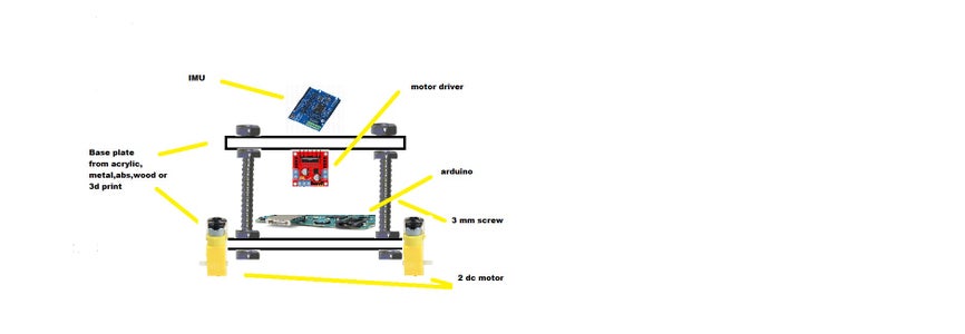
Step 1: Materials
The materials i used for this projects were the cheapest i could get,I buy from Chinese online store with lots of very cheap electronic ,arduino, drivers, sensors,… and free shipping hat’s good (free is good every time).
Battery: http://www.gearbest.com/rc-quadcopter-parts/pp_184809.html?lkid=10000465
Arduino uno http://www.gearbest.com/boards-shields/pp_235013.html?wid=8&lkid=10000466
Motor driver: http://www.gearbest.com/development-boards/pp_43069.html?lkid=10000467
IMU sensor:http://www.gearbest.com/sensors/pp_226745.html?lkid=10000468
2 Dc motorhttp://www.gearbest.com/other-accessories/pp_241581.html?lkid=10000469
Price summary:
arduino uno =3.47$
battery=1.99$
motor driver =4.86$
imu sensor=8.15$
2 dc motor=4.56$
TOTAL=23.16$
I used materials as cheap if i could but you can use whatever you have,
Step 2: Phisics
The physics for this robot are simple, the robot stand in two points
lined, the wheel, and i tends to fall and lose his verticality, the movement of the wheel in the direction of the falling rises the robot for recover the vertical position.
The vehicle attempts to correct for an induced lean angle by moving
forward or backwards, and the goal is to return itself to vertical.
There is a library for arduino that implements this method.
Step 3: Electronics
The electronics we are going to use in the project are simply three, an arduino UNO,
a motor driver and a IMU.
We use a motor driver based on the chip L298.
For the IMU i used the cheapest 10DOF (10 Degrees Of Freedom) i find,
the chinese GY-80 with 3-axis accelerometer, 3-axis gyroscope, magnetometer, barometer and temperature sensors. We use only accelerometer and gyro so you can save money buying another IMU, like the MPU-6050, a 6DOF IMU for only 3.63€!!!!, or accelerometer and gyro for separate.
The IMU is connected to the arduino 2 wires for communication (SDA and SCL) and 2 wires for power, it use 3.3V so we need 3.3V wire and GND.
The motor driver take power directly form the battery so don’t have to
connect arduino’s power to it (i mean the 5V form the arduino), but we need 6 wires to control it, 3 for each motor, one for send the PWM signal for control the motor velocity, and for indicate the direction we want the motor to spin.
The schematis is in the video how to wire the robot.

Participated in the
Sensors Contest 2016

Participated in the
Automation Contest 2016


