

Introduction: Nestuino


Based on Arduino Due
Inspired by Nest
Feature :
Temperature and Humidity, Light Sensor,Smoke sensor, alarm, led, text indication and time display on LCD.
Allow Bluetooth connection on Android device so you can read more detail and control an LED on the unit to on/off.
LCD navigation buttons will give more detail reading of analog inputs, time and date, temperature and humidity.
(Rev2) added button to change time according to Day Light Saving Time.
Warning/Caution :
This project is a just a proof of concept and not to be used as an actual life saving device. The smoke sensor is probably is not calibrated properly by my method but it is good enough to distinguish between clear and smoke from a burning candle.
Future features to be added :
Install 2 RGB Leds that will allow one to be controlled from Bluetooth,
and another one to be controlled depending on the amount of ambient light.
Adding ESP8226-01 (wifi serial transceiver) and able to connect to it using Wifi instead of Bluetooth.
May be ability to program sensitivity from LCD and Bluetooth.
Step 1: Materials


1 Arduino Due board
1 Photo sensor
3 LED
1 Buzzer
4 channel Bi-level shifter from Adafruit
1 2k ohms resistor (for Buzzer)
1 10k resistor (for DHT11)
4 330 ohm resistors (all smaller depending on our LED size)
1 MQ-2 smoke sensors
1 RTC clock DS1307 kit from Adafruit
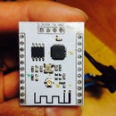
1 HC-05 Bluetooth serial
1 RGB LCD 16x2 with buttons from Adafruit
1 DHT11
1 old Smoke Alarm/Carbon monoxide for the case
(Rev2) 1 momentary push button
and of course some wires
Tools required
-soldering iron
-Dremel or any rotary cutting tools
The MQ2 sensors have a break in period and resistor that you can adjust for sensitivity. You can read more about how to adjust it on the internet.
On mine, I calibrate on a separate micropcontroller (ie. Uno) and just use a simpler/smaller code to read the digital and analog value. Using a candle and blowing it will give you the smoke. Then I put the sensor close to it and tweak the adjustment resistor until I see the LED turn on. Once you calibrate this, you can construct the bigger circuit on the Due.
Step 2: Circuit Setup

Using Fritzing. Connect the circuit as shown.
Test and download the program below and make sure it is working before you move everything to a permanent board/wiring.
Important notes :
- Make sure you use bidirectional level shifter for both SCL and SDA signals input.
- There are logic level shifter out there that only bidirectional on the TX channel only. This will not work.
Step 3: Download and Load the Code Into the Arduino Due
The program use several libraries from Adafruit. You can tell which one from opening my code.
I suggest you read the RTC DS1307 and Adafruit Backpack tutorial to get the proper library installed into your Arduino environment.
I did use a modified RCTlib.h to allow multiple device to talk using i2C on SCL1 and SDA1. See my previous post on the detail.
Load the program.
A lot of them I started from Adafruit Tutorial or someone else's in the Arduino forum. Thanks to all of them.
You are free to use and modify the parameters at your own risks.
To test, I temporarily put the code to allow if the photo sensor is sensing low light so you don't have to keep turning on a candle and blowing smoke to the MQ-2 sensor.
So in the code on line 129,130 and 203 and 204 , look for this
//if (MQ2_LED==0.00 or ambienlight<800){
if (MQ2_LED==0.00){
Change it to
if (MQ2_LED==0.00 or ambienlight<800){
//if (MQ2_LED==0.00){
Doing this will allow you to test the code simulating a gas alarm/detection/pick up without simulating real smoke/fire. Do remember to change them back so the device will work properly.
Attachments

Step 4: Test Using Serial Monitor

The code is setup to start serial monitor so go ahead and check Serial Monitor window. Use 115200 baud rate.
The above is what I am getting.
Step 5: Test Using Your Android Device With Bluetooth Terminal

I use a program called BlueTerm from the Android/Google-Playstore.
You can change the menu and what to display. Anything you send to Serial1 will show up here on the Bluetooth screen.
Step 6: Build Your Case


I used an old carbon monoxide alarm that is no longer working.
You can look at yours and see which part you want to cut out. On mine, I have to cut the battery container away.
I use #6-32 screw to hold the LCD at the bottom of the top cover and similarly the Due board is installed inside or on the bottom piece.
I have not quite figure out where to put all the sensors. I think I may just glue them under the top cover. I am not sure. I will update this post when it is done.
I decided to publish it since most of the code are done, it can easily be expanded to add more sensors and print in the Arduino IDE serial monitor, serial 1 (bluetooth) and LCD display. The framework is there. Just need to be creative.
The case will take a bit longer for me to finish since I am not very good with my tools so I want to take my time.
Enjoy and let me know if you have questions.


