

Introduction: Overview the Arduino Sketch Uploading Process and ISP


You can upload software to an Arduino using two methods. You may hear about the two methods commonly called ISP programming and FTDI or serial upload. I recommend learning about and becoming comfortable with using both methods. When I was getting started with Arduino, I wished for a guide or big picture of sketch uploading. Now here I am writing one. Glossary and Links are at the end. This is going to be rather long and detailed, so if you like that sort of thing, read on and enjoy. There's actually more than two methods, but more about that later.
Step 1: FTDI or Serial Upload

FTDI is actually a brand of chips. The FTDI company specializes in chips used to connect via USB. In Arduino land, USB-to-serial chips are used to interface a computer running the Arduino IDE to your Arduino's main processor for uploading new sketches and for interacting with your sketches via a serial monitor window. The USB-to-serial chip interfaces with the UART interface of the ATMEL processor on your Arduino.
In order for the Arduino to accept a sketch from the serial interface, it runs a program called a bootloader, which accepts the sketch and writes it into Flash memory. The bootloader actually resides in a small portion of the Flash memory in the upper range of memory addresses, which is reserved for bootloader use. As the bootloader program receives the sketch, it stores into the lower portion of Flash memory.
This serial programming uses a protocol called TTL serial. It is based on an old communication protocol called RS-232. RS-232 communications use voltages that change rapidly from a positive voltage of 3 to 25 volts, to a negative voltage of -3 to -25 volts. Personal computers typically no longer come with RS-232 interfaces, but they used to a few years ago. A PC with such an interface typically uses voltages that swing between 12 to -12 volts to send an RS-232 signal. The ATMEL processor on an Arduino uses signals in the 0 to 5 volt range. The version of this RS-232 protocol that is compatible with voltages in the range the Arduino processor can handle is called TTL serial, or sometimes you may hear it called TTL-232, or just serial.
Most Arduinos have a USB-to-serial adapter chip built-in, so you can connect the Arduino directly to your computer without any special interface or programmer. Some Arduinos, such as the LilyPad, Mini, and Pro Mini, don't come with a USB-to-serial adapter and you need to supply your own external one. The external adapters are very often called FTDI adapters, even if the brand of chip is not FTDI.
There are several wires or connections involved with serial communication. The most important ones are called RX (short for receive) and TX (short for transmit).
As the name implies, the RX wire or pin receives from another device. It listens for incoming communication. The TX wire or pin transmits data to another device. The TX wire from your USB-to-serial adapter rapidly switches between 0 and 5 volts in a pattern, and it is attached to the RX pin on the Arduino's processor, which is listening to those patterns.
The communication is two-way, so the Arduino's processor can send signals back to the USB-to-serial adapter. The processor uses it's own TX pin to send a signal to the USB-to-serial adapter's RX pin. The USB-to-serial adapter translates the signals back and forth between the Arduino and your computer through the USB cable.
The computer sends the sketch to your Arduino, and receives the sketch back from the Arduino so the computer can verify that the program loaded okay. The same serial connection can be used by your sketch running on the Arduino to communicate back to you via the serial monitor window. It is common to use this method to debug your sketches, because you can sprinkle Serial.print statements in your code in strategic places to report back the value of variables or to tell what your code is doing at the moment. And you can send data back to your computer, such as sensor or input pin readings. You can also send data from the computer to the sketch running on your Arduino using the serial monitor.
You may wonder how the Arduino knows when serial communication is trying to send it a sketch to load, or just communicating through the serial monitor with the sketch that is already running on the Arduino? The answer is simple. The bootloader program that accepts sketches and reprograms the Arduino only runs in the first couple of seconds after the Arduino's processor is reset. If the bootloader program running on the Arduino does not receive a certain sequence of characters indicating a sketch is attempting to upload, it quits running and starts the sketch that you loaded previously.
When Arduinos were first developed, the person uploading a sketch to the Arduino had to press the reset button on the Arduino right at the beginning of the upload process, and time it correctly, or try again. Later versions of Arduino made use of an additional serial protocol wire called DTR to reset the Arduino automatically. Since the DTR signal goes from 5V to 0 at the moment a new connection to the Arduino is started, if you send this signal to the reset line of the Arduino's processor, it resets. If reason the new serial connection is being established is because the Arduino IDE is sending a sketch to the bootloader, the bootloader goes ahead and accepts the sketch and stores it. If reason the new serial connection is being established is because you're opening the serial monitor of the Arduino IDE, then the Arduino resets, the bootloader runs just long enough to realize the IDE is not attempting to send a sketch, and the sketch you previously uploaded starts running.
It is useful to know about these signals such as the DTR signal used for automatic reset, especially if you want to correctly connect an USB-to-serial adapter to an Arduino that does not have the adapter built in, such as LilyPad, Mini, or Pro Mini. Or, if you want to troubleshoot problems with an Arduino, or program one Arduino using another. I mentioned in the previous paragraph the DTR signal goes from 5V to 0 at the moment a new connection is established. Well, this signal goes low and stays low for the entire time it is connected. If that signal were attached directly to the processor's reset pin, the processor would stay in a state of reset and would never get started running the bootloader or the sketch you uploaded previously.
So, here's the trick: The DTR signal is sent through a small capacitor to the reset pin of the processor. The capacitor turns the voltage from the DTR signal (which goes low and stays low) into a temporary spike that goes low to 0V and comes right back up to 5V. This resets the Arduino and lets it start the bootloader, which later starts the sketch.
A USB-to-serial adapter requires a driver to be loaded on your computer, so your computer will understand how to communicate with it. Genuine Arduinos use specific and finite list of models of USB-to-serial adapters so the IDE can be pre-packaged with all the drivers you may need. If you are using a clone, fake, derivative, home-made, or otherwise non-supported development board made by somebody other than arduino.cc or one of their partner manufacturers, that is actually just fine because it is open source hardware and software. Anybody can make one. But the board may use a USB-to-serial adapter that requires a driver for your computer and that is not included in the software download for the Arduino IDE. An example of this is the CH340G USB-to-serial chip that is very common on Arduino-compatible boards sold on eBay and Amazon. It is good for you to have knowledge of this so you prepare your computer with the correct driver.
This serial communication happening with the Arduino's processor usually happens through specialized pins on the processor that are specifically designed for TTL serial communication. The processor has special hardware called a UART, which handles sending the data out of the TX pin or receiving data on the RX pin. The logic for handling these signals is built-in to the processor at a very fundamental level. If you are not using the RX and TX pins on the processor for serial communication using the UART, the pins are available for doing other things, such as activating relays, transistors, LEDs, or receiving digital signals from sensors. They are just plain digital pins if not occupied with serial signals. Some processor chips have multiple UARTs and therefore several sets of RX and TX pins. Those pins are also plain digital pins if not being used by the UART part of the processor for serial communication.
A bootloader can be designed to accept sketches via any protocol using almost any pins on the processor. The processor has a variety of pins that are plain digital pins but those pins can optionally be used for specialized protocols. For example, there is a group of pins that can be used for IIC or I2C protocol, which is a special serial bus protocol capable of communicating with multiple devices. And there is another group of pins that can be used for the SPI protocol, which is yet another different serial bus protocol used to communicate with devices. The processor has special hardware designed to implement these different protocols on the various dedicated pins, and the logic for handling these signals is built-in to the processor at a very fundamental level.
Twister #1: These various protocols such as TTL serial, I2C, and SPI have the low-level logic built into the processor for handling the protocols if the specific pins for the protocol are connected to another device, but the protocols can be implemented to work on any of the digital pins on the processor by writing software that emulates the behavior of the processor's built-in logic circuits. This is called bit banging. A program can be written that drives the pins in a pattern that meets the requirements or specifications of the protocol. For example, a software serial protocol can be written that uses non-UART pins of the processor. The software then takes the place of hardware UART circuitry. This is useful if the pins you would normally use for a particular protocol are otherwise occupied, and you need to use other pins. Or, if you want to have more than the one built-in serial interface. For example, the ATmega328P processor has only one UART and it uses digital pins 0 and 1. It normally only communicates with one other serial device at a time. If you want to attach another serial device on pins 2 and 3, you can do that with a software serial program that bit-bangs the protocol. The Optiboot bootloader can be compiled to communicate through software serial on non-UART pins.
Arduinos commonly come with a serial bootloader installed, which uses the hardware UART onboard the ATMEL processor, and the Arduino IDE running on your computer is designed to communicate with that bootloader.
Twister #2: You don't need a bootloader! Read about ISP next.
Step 2: ISP Programming
ISP is also called ICSP. It is In-Circuit Serial Programming. This is a different kind of serial compared to TTL serial. It is SPI (Serial Peripheral Interface Bus) and uses 3 main wires to communicate for programming. When you program an Arduino's processor using ISP, usually the entire processor chip memory is erased, including the bootloader area, and your sketch is written. So, when you upload a sketch to the Arduino using ISP, the Arduino no longer has a bootloader on it. This means the next sketch you upload to it must also be uploaded using ISP. You can also use ISP to put a bootloader on the Arduino. This is called burning the bootloader. You may want to do this to change or upgrade the bootloader, or to restore the Arduino to normal operation after you have uploaded a sketch with ISP.
You may want to upload a sketch to an Arduino with ISP because you want your sketch to start right away after power on or reset, or because you don't want the bootloader on board to accept another sketch or to attempt using the serial pins or to flash pin 13.
To do ISP programming, you need an ISP programmer. There are numerous programmers compatible with Arduino, and they are usually a small device that plugs into USB or fits on the end of a USB cable, and they have a connector or wires that lead to your Arduino. It is common to connect the programmer to the ICSP header on your Arduino, which is a group of male pins arranged in 3 rows of 2 pins.
You can also use an Arduino as an ISP programmer, to program another Arduino. The Arduino IDE comes with an example sketch called ArduinoISP, which you can upload to your Arduino, and then it becomes an ISP programmer. In the Arduino IDE, in the menu under Tools, Programmer, select "Arduino as ISP." Since you can get a clone Nano, or Pro Micro, or other Arduino for just a few dollars, there is little need to buy a dedicated ISP programmer device unless it is for convenience.
So, if you have two Arduinos, go ahead and get started and try out ISP programming. It is not likely you will mess up anything, and you will learn. To do this, open the ArduinoISP sketch, modify it if necessary, and upload it to and prepare the programmer Arduino. Then connect the programmer Arduino to the target Arduino, and program the target Arduino.
Step 3: Figuring Out What Pins to Use
To set up the wiring for ISP programming, you need to connect the MISO wire of the programmer to MISO of the target Arduino. Connect the MOSI wire of the programmer to MOSI of the target. Connect SCK to SCK. Connect 5V to 5V and connect GND to GND. Connect whatever pin you are using for slave reset to the RST pin of the target. To help you understand and figure all this out, the next few paragraphs will give a lot of detail.
Note that in some tutorials, schematics, and datasheets you may see SCK or SCLK. Those labels are both abbreviations for the same function, Serial Clock. In this Instructable I use SCK.
Starting with the UNO, if you look at the UNO ICSP header pin arrangement on the board and on the schematic, you can figure out that the pins are numbered like this:
D12 MISO 1  .  .  2 VCC
D13  SCK 3  .  .  4 MOSI D11
     RST 5  .  .  6 GND
On the board there should be a dot or square pad that shows you what pin 1 of the ICSP header is. On the UNO that is the top left corner of the header. On the UNO, all of the pins on the ICSP header are directly connected to, and are duplicates of pins available elsewhere on the board. Pin 1 of the header is a duplicate of digital pin 12; pin 3 is a duplicate of digital pin 13, and so on. This is why if you look at many tutorials on the web you will see they are showing use of pins 11, 12, and 13 instead of using the ICSP header.
On all of the ATmega328P-based Arduinos, such as the Pro Mini, Mini, Nano, Duemilanove, and derivaties like RedBoard, Metro328, the same pin assignments apply. Use pins 10, 11, 12, and 13 if your Arduino does not have an ICSP header.
Looking at the Leonardo, you have to dig a little deeper than the schematic and board. The schematic is a little confusing because the processor is shown in two places, and the Arduino pin numbers of the MOSI, MISO, and SCK lines are not shown. You need to look at the variants/leonardo/pins_arduino.h file in the IDE application directory to figure out the pin numbers.
D14 MISO 1 . . 2 VCC
D15  SCK 3 . . 4 MOSI D16
     RST 5 . . 6 GND
When you look around the pins on the Leonardo, you can see digital pins 14, 15, and 16 are not available anywhere other than on the ICSP header. So, if you have a Leonardo, you can't exactly follow tutorials you find that show the connections to the outer edge pins 11, 12, and 13, and you must use the ICSP header. That means adapt the tutorial you are trying to use, using an adequate amount of knowledge you gained from reading this Instructable and by doing lots of research and reading to get familiar with your Leonardo.
On the ATmega32U4-based Arduinos such as Micro, Pro Micro, Esplora, use pins 10, 16, 14, and 15 if your Arduino does not have an ICSP header.
If you are using the ArduinoISP sketch that came with a version 1.6.5 or earlier of the Arduino IDE, the slave reset pin is not set to 10 by default when using a Leonardo. Read the rest of this step for details. If you are using version 1.6.6 or later of the Arduino IDE from arduino.cc you will notice the sketch just has the slave reset pin set to pin 10, so you can skip reading the rest of this step and move on to step 4.
Something you will find when digging into the Leonardo schematic and pins_arduino.h file is the SS pin is digital pin 17 and it goes to the RXLED and is not available on any header. The reason this is important becomes apparent when you load the ArduinoISP example sketch in the Arduino IDE and look at it. The RESET line is set to SS, which is pin 10 on the UNO, but pin 17 on the Leonardo. This is the wire you need to connect to the target Arduino's RST pin. So, in order to use this sketch on the Leonardo, you need to use an available pin you can actually connect to. Change the line:
#define RESET SS
to
#define RESET 10
Instead of using the pin by name SS, we will assign it to a specific pin number. Use pin 10, that way you can use the modified sketch on any Arduino. I think perhaps the sketch should have been written to send the reset signal from pin 10 instead of the SS pin anyway.
Step 4: Uno to Leo
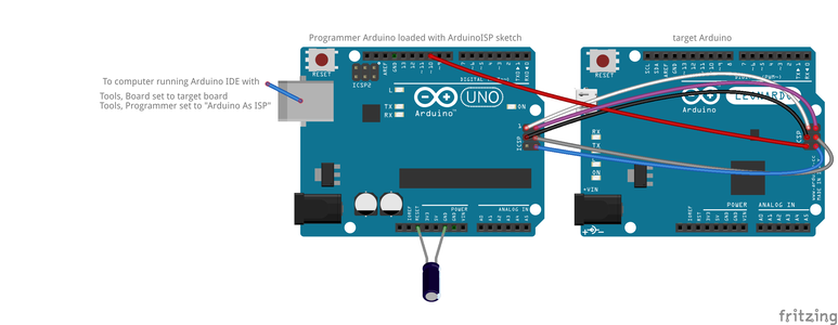
Let's examine how to use the UNO as an ISP programmer to program a Leonardo. Connect all pins of the ICSP header on the UNO to the ICSP header on the Leonardo, except pin 5, the RST pin. Connect pin 10 of the UNO to the RST pin (pin 5 of the ICSP header) on the Leonardo. When you do this you will end up with these connections:
- Pin 11 MOSI on programmer UNO to pin 16 MOSI on target Leonardo
- Pin 12 MISO on programmer UNO to pin 14 MISO on target Leonardo
- Pin 13 SCK on programmer UNO to pin 15 SCK on target Leonardo
- Pin 10 on programmer UNO to RST pin on target Leonardo
- VCC on programmer UNO to VCC on target Leonardo
- GND on programmer UNO to GND on target Leonardo
Connect the UNO to the computer via USB. Upload the ArduinoISP sketch to the UNO, then disable automatic reset upon serial connection by connecting a 10uF or larger capacitor between the RST and GND. The striped or negative lead of the capacitor goes to GND. This will prevent the UNO from resetting and interrupting the ISP programming process when the computer sends the program data through the UNO to the Leonardo.
Your wiring will look like the above diagram.
In the Arduino IDE menu go to Tools, Board, and select Leonardo. Go to Tools, Programmer, and select Arduino as ISP. Go to Tools, Port and make sure the port of the UNO you are using as the ISP programmer is selected. Open the example Blink sketch. Go on the menu to Sketch (or File on IDE 1.6.4 and older) and click Upload Using Programmer. After a few seconds the blink sketch should upload to the Leonardo and the LED should start blinking. What you have done is erased the Leonardo and installed the blink sketch using ISP. The Leonardo no longer has a bootloader.
As covered earlier, this means the next sketch you upload to it must also be uploaded using ISP. From now on you must use ISP to program the Leonardo. To verify that, you can go ahead and disconnect the Leonardo and hook it up with a USB cable and attempt to upload a sketch to it using the upload process. You will find that it doesn't work.
If you miss just getting out the USB cable and uploading sketches, you can use ISP to put a bootloader back on the Leonardo. This is called burning the bootloader. This will restore the Leonardo to normal operation.
Connect the UNO you are using as an ISP programmer up to the Leonardo just like you had it before when you uploaded the blink sketch. This time, go on the menu to Tools, Burn Bootloader. After a few seconds you should see the message Done Burning Bootloader near the bottom of the IDE. A fresh bootloader has been installed on your Leonardo. You can now hook up the Leonardo with a USB cable and upload a sketch to it using the upload process.
Step 5: Leo to Uno
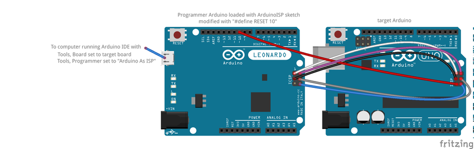
Now examine the reverse, using Leonardo as an ISP programmer to program an UNO. Connect all pins of the ICSP header on the Leonardo to the ICSP header on the UNO, except pin 5, the RST pin. Connect pin 10 of the Leonardo to the RST pin (pin 5 of the ICSP header) on the UNO. When you do this you will end up with these connections:
- Pin 16 MOSI on programmer Leonardo to pin 11 MOSI on target UNO
- Pin 14 MISO on programmer Leonardo to pin 12 MISO on target UNO
- Pin 15 SCK on programmer Leonardo to pin 13 SCK on target UNO
- Pin 10 on programmer Leonardo to RST pin on target UNO
- VCC on programmer Leonardo to VCC on target UNO
- GND on programmer Leonardo to GND on target UNO
And it will look like the above diagram.
Remove the capacitor from the UNO. You don't need that any more.
Connect the Leonardo to the computer via USB. Upload the ArduinoISP sketch to the Leonardo. If you are using the ArduinoISP sketch that came with a version 1.6.5 or earlier of the Arduino IDE, make sure you have modified the example sketch to use pin 10 as the RESET-sending pin as discussed in step 3. You do not need to disable automatic reset when using a Leonardo as an ISP programmer.
In the Arduino IDE menu go to Tools, Board, and select UNO. Go to Tools, Programmer, and select Arduino as ISP. Go to Tools, Port and make sure the port of the Leonardo you are using as the ISP programmer is selected. Open the example Blink sketch. Go on the menu to Sketch (or File on IDE 1.6.4 and older) and click Upload Using Programmer. After a few seconds the blink sketch should upload to the UNO and the LED should start blinking. What you have done is erased the UNO and installed the blink sketch using ISP. The UNO no longer has a bootloader.
To put the bootloader back on the UNO and restore it to normal operation, go on the menu to Tools, Burn Bootloader.
Windows users need to include an extra one-time step. Create a custom programmers.txt entry for Leonardo as ISP, so you can specify the arduino protocol instead of stk500v1 protocol. The details of this are discussed here by PeterVH: https://petervanhoyweghen.wordpress.com/2012/09/16/arduinoisp-on-the-leonardo/
Step 6: Details of ISP
My hope is after reading these details about the ISP process and somewhat detailed explanation of the pins and how to connect the Arduinos, you will have enough information to be comfortable with the ISP process. This Instructable was not intended to be a recipe to follow and blindly hook up the pins and hope for the best. You can now figure out how to connect any Arduino to any other Arduino, and burn a fresh bootloader or upload a sketch. I hope my method for explaining this has resulted in success and comfort with the process.
Can you figure out how to burn a bootloader or upload a sketch using ISP onto a Pro Micro, which is an ATmega32U4-based Arduino just like the Leonardo? It does not have an ICSP header, but it does have the pins numbered 14, 15, and 16.
How about using an UNO as ISP programmer to burn a bootloader or upload a sketch to a Nano or Pro Mini, which are both based on the ATmega328P just like the UNO? The Nano has an ICSP header, but if it does not have pins soldered on the header, can you use pins 11, 12, and 13 instead, and adapt?
How about using a Mega2560 as an ISP programmer or target? The Mega board is based on the ATmega2560 processor. The ISCP header is arranged like this:
50 MISO . . VCC
52  SCK . . MOSI 51
    RST . . GND
If you use the modified ArdinoISP sketch when using the Mega2560 as a programmer, you can use pin 10 as the RESET-sending pin, which you would connect to the target Arduino's RST pin. If you use an unmodified ArduinoISP sketch, you need to know that SS on the Mega2560 is pin 53. That detail is in the comments inside the ArduinoISP sketch. The ArduinoISP sketch that came with a version 1.6.6 or earlier of the Arduino IDE from arduino.cc have the RESET-sending pin set to 10 already. See step 3 for details about version 1.6.5 and earlier.
Step 7: The Other Protocol, CDC-serial
Remember when I said there are two methods for uploading software to an Arduino? Well, I may have fibbed a little. Here is a third. Some models of Arduino, such as Leonardo, Pro Micro, Micro, Robot, Esplora, have an ATmega32U4 processor. It has pins for the USB protocol and has low-level logic designed specifically to interface with USB. What this means is there is no USB-to-serial adapter or chip at all, and the ATmega32U4 is connected directly to USB of your computer.
The information is passed between the computer and the Arduino using a protocol that mimics or stands in for TTL serial, but there are no exposed pins for RX and TX involved. The RX and TX pins on the Leonardo and other ATmega32U4-based Arduinos are not involved at all in the bootloader or upload process. The USB connection is a kind of firmware-implemented UART0 that is used in your sketches with statements like Serial.print. The RX and TX pins are connected to a secondary UART, which is UART1, and are used in your sketch with statements like Serial1.print.
Since the USB CDC-serial interface does not have physical pins such as RX and TX and the other related TTL-232 pins, we don't have access to a DTR pin to reset the Arduino and make it run the bootloader. The USB pins are simply D+ and D-. What do we do about that? The Leonardo designers thought long and hard about this and came up with an interesting work-around. Although the CDC-serial interface in the ATmega32U4 processor does not really use baud rates like serial lines do, it is aware of when the computer is requesting to set a particular baud rate. They programmed the Arduino IDE to do a baud rate change to 1200 for just a second and then change it to 57600. This is called a 1200bps_touch and you can see the setting if you study the boards.txt file that is part of the Arduino IDE software package. The Leonardo detects this and resets the processor using a watchdog method. Then the bootloader runs. The bootloader is called Caterina. It is different from the ATmega328P-based Arduinos in that it does not accept the sketch using the RX and TX lines. Caterina uses the USB D+ and D- lines.
So, the Leonardo and other ATmega32U4-based Arduinos do not reset when you open serial monitor or start some other serial process with them. They only reset when the IDE does the 1200bps_touch just before uploading a sketch. That is why you don't need to disable automatic reset with a capacitor when you use it as a programmer.
Step 8: UNO and Mega2560
Ok, since I kind of fibbed before, I'll come clean and describe yet another one. The UNO and Mega2560, if they are genuine or clones, use ATmega16U2 processors for the USB-to-serial chip. This is just to carry the uploads of sketches and other serial traffic between your computer and the main processor. That is what the stock firmware on the ATmega16U2 does. The main processor on the UNO is the ATmega328 and main processor on the Mega2560 is the ATmega2560. The main processor is where your sketch runs.
Let's back up a little and talk some more about the ATmega16U2 processor used as the USB-to-serial chip. It is very similar to the ATmega32U4 that is used as the main processor of the Leonardo. Advanced users can program it to do interesting things that a Leonardo can do, such as move the mouse cursor on the connected computer, or to simulate a keyboard and type on the connected computer. The point is, it is programmable.
The ATmega16U2 has a bootloader. This bootloader is not programmable directly from the Arduino IDE, so the people doing the hacking to make this ATmega16U2 do tricks use the command line, or add customizations to the IDE, or use a program called FLIP. The bootloader protocol is called DFU, and it is the default bootloader provided by ATMEL for this chip. You upload to it using a Windows program called FLIP, or a Mac/Linux program called dfu-programmer.
Or, you can use ISP programming to upload to it, which would erase the chip and install your program or a replacement bootloader. You may have noticed this other ICSP header on the UNO and Mega2560, right next to the USB connector. I cover the concept of ISP programming the ATmega16U2 to restore the stock firmware on the UNO in another Instructable.
Step 9: Miscellaneous Extra Stuff
As I mentioned earlier, the bootloader resides in a small portion of the upper range of Flash memory. The bootloader section of Flash memory is set in special registers called fuses which tell the processor how large the bootloader is and where to find it to start running it upon power up or reset. As the bootloader program receives the sketch, it stores into the lower portion of Flash memory. A sketch you have loaded into Flash memory can't usually alter itself or the bootloader, nor can it write to unused parts of Flash memory. Only programs running in the reserved bootloader area can write to Flash memory. Advanced users can put a small snippet of code into the bootloader area of memory and have it sitting there, co-residing with the bootloader, and call it from their program running in the lower portion of Flash memory, thus allowing their program to write to Flash memory.
Since the genuine or clone UNO and Mega 2560 come with a programmable USB-to-serial processor, it is possible to upload a program to that processor to act as an ISP programmer, and connect it to the UNO's or to the Mega's main processor and re-burn it's bootloader or load a sketch via ISP. Or you can upload a sketch to the main processor that re-programs the USB-to-serial processor via ISP. This is sometimes called UNO self-ISP.
You can also use an FTDI USB-to-serial converter as an ISP programmer using a program on your computer that bit-bangs the ISP protocol to the FTDI converter's pins.
These alternate ISP methods are mostly academic pursuits, because it is easier and inexpensive to use an ISP programmer device or to use another Arduino as an ISP programmer. But if you are locked in a burning building with nothing but limited Arduino hardware, your buddy MacGyver, nail clippers, and a matchbook, you can do ISP programming and may still have time to escape before the fireball explosion.
It is possible to use the Optiboot bootloader on the ATmega32U4-based Arduinos, to upload sketches through the TTL serial RX and TX pins. Then you would need to use an external USB-to-serial adapter or other serial device to upload, and not use the USB port of the ATmega32U4 processor. I cover that concept in another Instructable where I show how to use a Bluetooth module to upload to a Leonardo. I keep telling you one more thing... Well, that's yet another way to upload a sketch to Arduino: through a Bluetooth or other wireless serial device.
It is also possible to make a virtual USB port on a processor such as ATmega328P. In Adafruit's Pro Trinket, there is no USB-to-serial chip, but there is a USB port anyway. How did they do that? What they've done is connect the digital pins 2 and 7 to the USB port, and then burned a special bootloader onto the chip that listens for USB signals on those 2 pins. There is no special hardware inside the chip that reads those signals, so the bootloader includes special code that figures out the signals and accepts a sketch. That is yet another way to upload a sketch.
When you click on the upload button in the Arduino IDE, or when you go on the menu to File or Sketch and click on Upload, the USB-to-serial upload method is the default method used for most boards. When you go on the menu to Sketch (or File on IDE 1.6.4 and older) and click on Upload Using Programmer, that is when the IDE attempts to use your ISP programmer or Arduino as ISP, to upload a sketch via ISP. Here is one more tidbit you can research and play with. If you want the upload button to do ISP programming to upload to a target board, you can create a custom boards.txt entry. There are settings in the entry that determine which upload method is used, serial or ISP.
Here is a tidbit that I hope clarifies instead of confuses. I think it is unfortunate that Arduino made an ISP programmer device called ArduinoISP, and when you use it you need to select on the menu Tools, Programmer, ArduinoISP. That device is discontinued as far as I know, but is it still available through some stores. It is unfortunate wording and potentially confusing because when using an Arduino as ISP you load the sketch called ArduinoISP and select on the menu Tools, Programmer, Arduino as ISP.
Step 10: Quick Glossary and Links
ATMEL -- The company that manufactures the popular processor line used in Arduinos
Caterina -- A bootloader program used to upload software to FLASH memory via a USB connection using the avrdude program
DFU -- Device Firmware Upgrade, a bootloader program used to upload software to FLASH memory via a USB connection using the dfu-programmer or FLIP program
FLASH memory -- A special type of EEPROM (Electrically Erasable Programmable Read-Only Memory) that is used to store a bootloader and sketch on an Arduino
FTDI -- Future Technology Devices International, the company which manufactures popular USB-to-serial chips used in many Arduinos and accessories
Header -- A row of pins or sockets used to conveniently connect and disconnect wires or plug in devices without soldering
IDE -- Integrated Development Environment, an all-in-one program providing a sketch editor, compiler, debugging serial monitor, and uploader
IIC or I2C or 2-wire serial -- Inter-Integrated Circuit, a serial protocol
ISP and ICSP -- In-system programming, also called In-Circuit Serial Programming
Optiboot -- A bootloader program used to upload software to FLASH memory via a TTL serial connection using the avrdude program or the IDE
Serial -- A protocol that sends data across a wire one bit after another
SPI -- Serial Peripheral Interface Bus, a serial protocol
TX and RX -- Transmit and Receive wires of the RS-232 or TTL-232 serial protocol
UART -- Universal Asynchronous Receiver/Transmitter, a hardware device for translating between serial and parallel data
USB -- Universal Serial Bus, a serial protocol and standard for connector and cable design
.
.
Mess of useful links in no particular order
http://www.gammon.com.au/breadboard
http://www.gammon.com.au/bootloader
http://www.atmel.com/images/doc0943.pdf
https://www.sparkfun.com/tutorials/215
http://www.atmel.com/images/doc0943.pdf
http://www.atmel.com/webdoc/stk500/stk500.highVoltageProgramming.html
http://www.atmel.com/images/doc0943.pdf
https://learn.adafruit.com/ftdi-friend/ftdi-friend-vs-avr-programmer
http://www.atmel.com/images/doc0943.pdf
http://forum.arduino.cc/index.php?topic=48784.0
http://www.atmel.com/images/doc0943.pdf
http://forum.arduino.cc/index.php?topic=321783.0
http://www.atmel.com/images/doc0943.pdf
http://www.atmel.com/images/doc0943.pdf
http://www.gammon.com.au/forum/?id=11643
http://forum.arduino.cc/index.php?topic=332191.0
https://petervanhoyweghen.wordpress.com/2012/09/16/arduinoisp-on-the-leonardo/


