

Introduction: PIR Sensor for DSLR Photo Camera


Long story short: it was needed to take outdoor pictures every time when an animal was approaching a DSLR camera, so I built a box with a PIR sensor and a small Arduino Pro Mini to control the camera.
The remote controls used for DSLRs / mirorrless cameras are in general basic devices: you have there 1 switch for focus and 1 switch for shutter, if you press them in this order (focus -> shutter), it is like when you press the button on the camera (half way is the focus and full way is the shutter). The camera must have a remote control port in order to connect the remote control, some may have radio remote controls, some may have infrared remote controls.
For my was the case to use a Canon DSLR with a remote control port (a 2.5mm 3-contacts connector type).
Step 1: Electrical Diagram

Electrical diagram made in KiCAD - it is an amazing mature opensource environment where you can draw schematics and printed circuits as well, no layer or board size limitations - you should try it.
The way the remote control port works on the camera is very simple: tie focus pin to camera ground and camera will focus, tie afterwards the shutter pin to ground and camera will take a crisp focused picture. Focus time may vary, sometimes the camera won't be able to focus, so this needs to be considered. As well you can use camera in manual focus mode, camera will ignore the focus signal and take a picture when shutter signal is provided.
I used an Arduino Pro Mini (clone) on 5 Volt logic level in order to provide the focus and shutter signals and I connected the PIR sensor on digital pin 2, I used pin 2 external interrupt to wake up Arduino from sleep mode in order to save battery.
The focus and shutter signals came from digital pins 4 and 9 on Arduino (because was easy to solder the wires there). Focus signal is 1 second long, then it is a 0.5 s delay, then shutter signal is released for 0.5 s.
Since it is not good to mess up with expensive electronics (aka to apply direct Arduino voltages to the camera), I decided to use a pair of N-channel MOS-FETs which are acting as switches (BS107), mounted on a perforated proto board (you can use as well relays, but they are noisy, it can scare your photo subject).
The 2 transistors are feeding focus and shutter signals to the camera through a 3.5mm female connector (I manufactured a 3.5mm male to 2.5mm male cable).
In order to know what is going on, I used a bi-color LED on digital pins 6 and 7, red color means that the focus signal is released, then green color will be on half a second to indicate that shutter signal was released. In the end will be 0.5 s orange color (because green + red will result in orange light :) - I have no other explanation why I use it :) ).
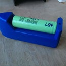
For power, I used a cheap external cell phone battery with microUSB / USB charger, it is using a single 18650 Lithium battery.
Step 2: Creating the Housing for the PIR Sensor

I used a plastic box (8cm by 8cm and 5cm height), it is rain proof, I had to drill various holes on it for PIR sensor, connectors, LEDs - look at the images and read further on to understand what is about.
Unfortunately I missed taking a picture of the plastic box before start working on it, but I gave my word that was without holes initially :)
Step 3: Fit the PIR Sensor Into the Plastic Box


I drilled a hole big enough to fit the Fresnel lens on the plastic box and I used hotmelt for keeping the PIR sensor there and to seal the box from rain.
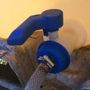
Step 4: Add Power Connector, Remote Control Connector and Nut for Tripod


That is pretty simple as well, one hole for the 5mm female connector, one hole for the 3.5mm female connector and I used 3 screws for the tripod nut. All was dipped into hotmelt :)
Step 5: Adding the ON/OFF Switch and the Status LED


Since I was missing a rain proof power switch (ON/OFF), I used a 2.54mm jumper and header (2 pins), I drilled 2 small holes on the plastic box and I used some hotmelt to make it rain proof and as well to make a BIG jumper, this jumper will be tied to the box in order to avoid losing it..
Step 6: Making the Charging Cable and the Remote Control Cable


I made 2 cables and I used previous experience from this instructable about making long lasting cables:
-one to charge the battery for the PIR sensor. It is a simple cable with 2 wires, at one end it is a USB connector, at the other end it is a 5mm male connector. You have to match the +5 Volt and GND from the USB pinout with the 5mm male connector, Google it :)
-a second cable is the remote control cable. For the Canon DSLR it is simple: on the PIR sensor end it is a 3.5mm male jack (3 contacts) and on the camera end it is a 2.5mm male jack (1 to 1 compatibility).. For this one you have to Google as well, it depends on your camera model what you need and how to connect everything.
Step 7: Connecting Electronics Together


As I said, I used an Arduino Pro Mini, to this board I soldered the programming header (I used a USB to serial cable for programming).
For the transistor switches I used a small piece of perforated board.
I soldered wires according to the schematic, I used some hot melt to keep in place 18650 Lithium battery, to keep in place the microUSB / USB charger (to align the LED with the hole on the plastic box).
I made a short cable to connect the PIR sensor, I soldered wires for the bi-color LED.
In the end resulted a mess :), thanks God that I put it on a box and it is not so visible.
Step 8: Check That Various Functional Blocks Are Working Separately
It is always good to check things separately.
-check that the 18650 battery is charging (don;t forget to use the BIG jumper to close the circuit)
-check that the 18650 step-up electronics is providing +5 Volt
-check that PIR sensor, Arduino are powered
-make sure that all devices are correctly connected to GND
-modify blink sketch for Arduino in order to turn on and off the bi-color LED
-modify blink sketch for Arduino in order to turn on and off the transistor switches
-modify the button sketch and make sure that the PIR signal will be read by Arduino and turn on a LED if so
If all these are working, than things are heading to a good direction :)
Step 9: Complete Software for the PIR Sensor
After making sure that all things are working, we can program the complete software. I used a nice sleep module in order to save battery power, here is library Sleep_n0m1.
The software is pretty straight forward:
-at initialization, the bi-color LED will blink 10 times
-after this moment, PIR sensor is fully operational
-when PIR sensor is detecting a change, it will wake up the Arduino and Arduino will give the focus signal to the camera (1 second), then it will wait 0.5 seconds and then give the shutter signal (0.5 seconds)
-camera will take a photo.
******************************************************************************************
#include Sleep_n0m1.h
// Milliseconds of signal activation
const int FOCUS_TIME = 1000;
const int SHUTTER_TIME = 500;
// Digital out pins
const int FOCUS_LED = 7;
const int SHUTTER_LED = 6;
// Digital in pins
const int PIR_IN = 8;
// Digital out pins (to MOS-FET transistors)
const int FOCUS_ON = 4;
const int SHUTTER_ON = 9;
Sleep sleep;
// One time set up
void setup() {
pinMode( FOCUS_LED, OUTPUT );
pinMode( SHUTTER_LED, OUTPUT );
digitalWrite( FOCUS_LED, HIGH);
digitalWrite( SHUTTER_LED, HIGH);
pinMode( FOCUS_ON, OUTPUT);
pinMode( SHUTTER_ON, OUTPUT);
digitalWrite( FOCUS_ON, LOW);
digitalWrite( SHUTTER_ON, LOW);
pinMode( PIR_IN, INPUT );
delay(2000);
//****************turn-on red, green and amber LED
//for 10 times - 1st time
digitalWrite( FOCUS_LED, LOW);
delay(500);
digitalWrite( FOCUS_LED, HIGH);
digitalWrite( SHUTTER_LED, LOW);
delay(500);
digitalWrite( SHUTTER_LED, HIGH);
digitalWrite( FOCUS_LED, LOW);
digitalWrite( SHUTTER_LED, LOW);
delay(1000);
digitalWrite( FOCUS_LED, HIGH);
digitalWrite( SHUTTER_LED, HIGH);
//****************2nd time
digitalWrite( FOCUS_LED, LOW);
delay(500);
digitalWrite( FOCUS_LED, HIGH);
digitalWrite( SHUTTER_LED, LOW);
delay(500);
digitalWrite( SHUTTER_LED, HIGH);
digitalWrite( FOCUS_LED, LOW);
digitalWrite( SHUTTER_LED, LOW);
delay(1000);
digitalWrite( FOCUS_LED, HIGH);
digitalWrite( SHUTTER_LED, HIGH);
//****************3
digitalWrite( FOCUS_LED, LOW);
delay(500);
digitalWrite( FOCUS_LED, HIGH);
digitalWrite( SHUTTER_LED, LOW);
delay(500);
digitalWrite( SHUTTER_LED, HIGH);
digitalWrite( FOCUS_LED, LOW);
digitalWrite( SHUTTER_LED, LOW);
delay(1000);
digitalWrite( FOCUS_LED, HIGH);
digitalWrite( SHUTTER_LED, HIGH);
//****************4
digitalWrite( FOCUS_LED, LOW);
delay(500);
digitalWrite( FOCUS_LED, HIGH);
digitalWrite( SHUTTER_LED, LOW);
delay(500);
digitalWrite( SHUTTER_LED, HIGH);
digitalWrite( FOCUS_LED, LOW);
digitalWrite( SHUTTER_LED, LOW);
delay(1000);
digitalWrite( FOCUS_LED, HIGH);
digitalWrite( SHUTTER_LED, HIGH);
//****************5
digitalWrite( FOCUS_LED, LOW);
delay(500);
digitalWrite( FOCUS_LED, HIGH);
digitalWrite( SHUTTER_LED, LOW);
delay(500);
digitalWrite( SHUTTER_LED, HIGH);
digitalWrite( FOCUS_LED, LOW);
digitalWrite( SHUTTER_LED, LOW);
delay(1000);
digitalWrite( FOCUS_LED, HIGH);
digitalWrite( SHUTTER_LED, HIGH);
//****************6
digitalWrite( FOCUS_LED, LOW);
delay(500);
digitalWrite( FOCUS_LED, HIGH);
digitalWrite( SHUTTER_LED, LOW);
delay(500);
digitalWrite( SHUTTER_LED, HIGH);
digitalWrite( FOCUS_LED, LOW);
digitalWrite( SHUTTER_LED, LOW);
delay(1000);
digitalWrite( FOCUS_LED, HIGH);
digitalWrite( SHUTTER_LED, HIGH);
//****************7
digitalWrite( FOCUS_LED, LOW);
delay(500);
digitalWrite( FOCUS_LED, HIGH);
digitalWrite( SHUTTER_LED, LOW);
delay(500);
digitalWrite( SHUTTER_LED, HIGH);
digitalWrite( FOCUS_LED, LOW);
digitalWrite( SHUTTER_LED, LOW);
delay(1000);
digitalWrite( FOCUS_LED, HIGH);
digitalWrite( SHUTTER_LED, HIGH);
//****************8
digitalWrite( FOCUS_LED, LOW);
delay(500);
digitalWrite( FOCUS_LED, HIGH);
digitalWrite( SHUTTER_LED, LOW);
delay(500);
digitalWrite( SHUTTER_LED, HIGH);
digitalWrite( FOCUS_LED, LOW);
digitalWrite( SHUTTER_LED, LOW);
delay(1000);
digitalWrite( FOCUS_LED, HIGH);
digitalWrite( SHUTTER_LED, HIGH);
//****************9
digitalWrite( FOCUS_LED, LOW);
delay(500);
digitalWrite( FOCUS_LED, HIGH);
digitalWrite( SHUTTER_LED, LOW);
delay(500);
digitalWrite( SHUTTER_LED, HIGH);
digitalWrite( FOCUS_LED, LOW);
digitalWrite( SHUTTER_LED, LOW);
delay(1000);
digitalWrite( FOCUS_LED, HIGH);
digitalWrite( SHUTTER_LED, HIGH);
//****************10th time and over
digitalWrite( FOCUS_LED, LOW);
delay(500);
digitalWrite( FOCUS_LED, HIGH);
digitalWrite( SHUTTER_LED, LOW);
delay(500);
digitalWrite( SHUTTER_LED, HIGH);
digitalWrite( FOCUS_LED, LOW);
digitalWrite( SHUTTER_LED, LOW);
delay(1000);
digitalWrite( FOCUS_LED, HIGH);
digitalWrite( SHUTTER_LED, HIGH);
}
void loop() {
sleep.pwrDownMode(); //set sleep mode
sleep.sleepInterrupt(0,RISING); //(interrupt Number 0 (or pin 2), interrupt State on rising)
doFocus();
doShot();
delay(1000);
}
// Sending focus signal
void doFocus() {
digitalWrite( FOCUS_LED, LOW);
digitalWrite( FOCUS_ON, HIGH );
delay( FOCUS_TIME );
digitalWrite( FOCUS_ON, LOW);
digitalWrite( FOCUS_LED, HIGH);
delay(200);
}
// Sending shutter signal
void doShot() {
digitalWrite( SHUTTER_LED, LOW);
digitalWrite( SHUTTER_ON, HIGH );
delay( SHUTTER_TIME );
digitalWrite( SHUTTER_ON, LOW );
digitalWrite( SHUTTER_LED, HIGH);
delay(100);
//amber color
digitalWrite( FOCUS_LED, LOW);
digitalWrite( SHUTTER_LED, LOW);
delay(1000);
digitalWrite( FOCUS_LED, HIGH);
digitalWrite( SHUTTER_LED, HIGH);
}
Step 10: Conclusion
The PIR sensor has 2 trims where you can control the sensitivity and the delay, I left delay on minimum, so the PIR will provide a 2 seconds long signal to Arduino, the sensitivity is something you have to adjust based on your needs.
One additional thing: I put a nut to attach the device to a tripod screw (1/4" diameter, 20 threads per inch). I was thinking as well that I can make an adapter to put the PIR shutter on a flash shoe, directly on the camera (without electrical connections, just to let it there).
It should be possible to use this PIR sensor for video recording, but software needs some changes (start recording, check after 5 seconds if there is any move, if no move, than stop recording etc)

Participated in the
Make a Box Contest


