

Introduction: Pandora's Clock: Nixie Tube Clock and Pandora Internet Radio


A Nixie Tube Clock featuring Pandora Internet Radio, based on the Raspberry Pi with a custom designed case, LCD display, WiFi connection, amplifier and speakers. This is the most unique clock radio you will ever find!
This is also quite possibly the most expensive thing I have built to date. That said, most of the cost is tied up into the Nixie tubes (Huge IN-18 Tubes in this case.) and the clock board itself. It would be possible to use a less expensive type of tube and board combination or possibly get rid of the clock portion all together and then you would just have another type of Pandora Box project.
The inspiration for this project came from several sources. The first of which is my love for old and new tech and the perfect combination of that comes in the form of Nixie tube clocks. The best clock kits I have found so far come from a web store called PV Electronics. PV Electronics is based out of the UK and appears to be a one man show, but the customer service is fantastic and the kits are inexpensive in comparison to other kits with the same features. Please go check them out and tell them I sent you!
The second source of inspiration came from fellow Instructables member "Ayy" who has a very popular Pandora's Box build. Though I ended up going a different route with the LCD and LCD control, I had originally planned to do it his way. It just turned out that the Adafruit Pi Plate and LCD kit was about the same cost as building it from scratch and it cost me much less time, which is at a premium for me these days. Please go over and check out his project, especially if you want to build just the Pandora Box and want to do it on the cheap!
All that said, this is mostly an Instructable on how to assemble everything. I didn't have the forethought to document every single step along the way. However, most of it will be pretty self explanatory if you order the exact parts and pieces that I ordered.
Let's get started!
Step 1: Parts and Tools Required and Cost


To build this EXACT clock, you will need the following Parts and Tools:
Parts:
- SPECTRUM IN-18 Nixie Clock kit from PV Elctronics$116.17
- Adafruit Pi Plate and 16x2 Blue and White LCD Kit$19.95
- Adafruit Stereo 3.7 Watt Amplifier$8.95 (You may want to use a 20 Watt Amp since mine seems quiet.)
- Raspberry Pi Model B+ (Or newer...) $29.95
- 12V DC Power Supply (Min. 2A)$6.22 (Or you can probably salvage one from the house...)
- 6 IN-18 Nixie Tubes$209 (Ebay is the best option, be sure to check seller ratings!)
- Pandora's Clock case cut by online service or your own laser cutter. $30 at Ponoko.com
- 2 moving coil speakers with suitable impedance value. I used some salvaged 8Ω speakers. $0-10
- 3 locking SPST button switches.$4.62 (For 5)
- 5 momenetary, normally open, tactile switches with extended posts. (The Adafruit Plate comes with tactile switches but they don't extend through the case. I used the included switches and glued extensions onto them. If I had to do it again I would buy more switches with the extensions already on, because they are $4.79 for 100.)
- A set of male header strips, $2.05 and various jumper wires. $9.99 (Buy a pack of 40 or so, you'll use them eventually...)
- Small bolts and nuts to attach case lid to the clock board. $0-3 (I found these laying in a parts bin in my house, not sure of the exact size. The mounting holes are about 2 mm though.)
- Wi-Fi USB Dongle for Raspberry Pi$7.99
- 8 GB or larger SD card for Raspberry Pi$5.95
- Heat shrink tubing to keep connections neat. $8.79
- Speaker Wire (Salvaged from other broken electronics in the house.)
TOTAL COST: $477.42Not Including shipping. (OUCH! But trust me when I say this: This is probably the coolest clock you will ever have.) Head over to my Etsy Page and I'll put one together for you if you're feeling generous!)
Tools:
- Soldering Iron
- Solder
- "Helping Hands" and Magnifier
- Wire Strippers
- Hot Glue Gun
- Small Screw Drivers (Flat and Phillips)
- Wood Glue
- Hobby knife
- Sandpaper
- Clamps
Step 2: Assemble the Spectrum Nixie Clock
CAUTION: Nixie tube clocks use high voltage; up to and over 300 Volts in some cases! This is enough to kill you or at the very least make you wish you hadn't touched that bare conductor with your hands. Use common sense, appropriate safety techniques, and follow the warnings and protocols from your kit instructions.
My father always said, "You can drink beer while working on cars, but not while working with electricity."
The first step is to assemble the Spectrum IN-18 Nixie clock from PV Electronics. The instructions are found on the website and are very thorough. If you have some experience with soldering this should prove very fun and easy for you to do. I won't get into specifics because from there it's a very straightforward build. However, I have attached a time lapse video of the clock assembly if you are interested.
This takes 3-4 hours depending on your skill level.
Step 3: Laser Cut Your Clock Case

I do not have a laser cutter. I really want one though...any donors?
Therefore, I used Ponoko.com, an online laser cutting service, to cut the case for me.
At Ponoko, you can upload your design file and they will cut it from the specified material for a fee, then ship it to your door. I've used their service twice now and it's been amazing!
I have attached the design file that I made in Ink Space. Ink Space is free software and I recommend you take a look at it for laser cutting and other projects; it is very robust.
I have attached the clock case design file to this project. You can simply upload the design and have it cut, or you can make modifications to it such as: custom engraving or decoration, different size holes for buttons and power adapter. If you change the design please send me a photo so I can see what you've come up with!!
I would advise you to have the design available on your PC and check the measurements with your clock board build in case you did not assemble it the same way as I did or if the board design changes over time. Or, at the very least, cut it out from cardboard and do a mock up. As it was, I went through 3 iterations before I got it perfect and that expense adds up! I used 3.0 mm thick Birch Plywood from Ponoko, click here to go straight to my design and order it up.
Step 4: Assemble Your Pi Plate and LCD


This is another simple board build, though I found in necessary to do some modifications to the steps from Adafruit.com to be sure that the Raspberry Pi would fit in the case and to remotely mount the buttons.
Here are the modifications:
- Do not install the tactile switches. Use thin gauge wire to remotely mount either the included switches or the ones you purchased with the extended posts to the board. Not all 4 terminals are used. If you look closely at BOTH sides of the board you will notice that only one terminal is used for the interface and one other is connected to the ground plane for each switch location. Solder two wires (About 3-4 inches long) to these 2 holes and then solder the other ends to 2 terminals on the same side for each tactile switch. Check with an electrical meter to make sure it works.
- Instead of attaching the LCD directly to the Pi Plate, install a male header strip on the LCD and use the female jumper ribbon to remotely connect the two. I directly connected mine to the LCD and it doesn't leave quite enough room to mount the buttons remotely in the case. I got it to work, but it wasn't fun. Remotely mounting it will make it much easier to deal with.
Here are the Adafruit Instructions.
When you're finished you can move on to setting up the Pianobar Software.
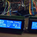
Step 5: Configure Raspberry Pi and Piano Bar


Again, there are already steps published to achieve this, so I won't reinvent the wheel here. Follow this instruction set from Adafruit.
This will take you all the way from setting up the Raspberry Pi operating system, to testing your LCD and buttons.
Use headphones or other powered speakers to test the audio, we will set up the amplifier and speakers next.
Beware of older instructions for setting up Pianobar, including all of the ones on Instructables. They don't work! They will only cause you to pull your hair out! Follow the Adafruit tutorial to the letter and you shouldn't have a problem!
Step 6: Build Amplifier and Connect Speakers to Raspberry Pi


Here are the instructions for the amplifier, pretty straightforward soldering.
3.7 Watt Amplifier Instructions
- Use two female jumpers for the VCC (5V DC) and GROUND PINS and these will attach to the clock board in a later step.
- Use four female jumpers for R-, R+, L-, and L+. Tie the two negative wires together and solder.
- The Right and Left signal wires will be soldered directly to the Raspberry Pi Board as shown in the photo, directly underneath the Raspberry Pi Audio Jack. (See below.)
- Then solder the two ground jumpers to the ground terminal under the Raspberry Pi Audio Jack
- You can use different connector combinations if you'd like to make these connections more or less permanent.
- Now you can simply place the speaker wires in the terminal blocks on the amplifier and screw them down tight. Then solder the wires to the speakers on the corresponding negative and positive terminals.
To connect the audio output from the Raspberry Pi to the amplifier you have 2 options:
- Solder R+, L+, and GND wires directly to the Pi board. (I did this.)
- Use a stereo mini jack in the audio connector on the Pi, strip the ends and connect to the amplifier. (I couldn't do this in my original clock because of where the Pi was mounted, I didn't have clearance.)
To solder directly to the Pi Board: (Look at the photo notes as well.)
Solder to Points C34 (Left +) and C48 (Right +). The center point closest to the jack can be used as Ground.
Step 7: Solder Headers to Clock Board for Power Access


To run everything (Raspberry Pi, LCD, Amplifier, etc.) we need to pull power from the clock board to avoid using two power supplies.
On the clock board you will notice "Test" points for GND, 12V, 5V, and HV (High Voltage, BE CAREFUL!)
These test points have through holes and are a convenient place to attach male header pins. Solder a pin to each of the GND and 5V test points. You will attach both the amplifier power and the Raspberry Pi power here so you need to build a pigtail of sorts to split it into 2 points. How you do this is up to you but I just tied 2 male header wires to a female header wire.
Now you have access to 5V DC and GND for your devices. The next step will show where to solder the power supply jumpers for the Raspberry Pi main power.
A note about power consumption: The spec sheet from PV Electronics recommends at least a 12V DC 1.0 amp power supply. Since we are attaching two more devices (Raspberry Pi w/ LCD and the amplifier.) I went with a 2.0 amp supply.
Step 8: Solder Power Connection for Raspberry Pi


Underneath the Raspberry Pi main board you will see two connection points labeled "D17" and "F3"
Solder stripped ends of 2 female jumper wires to these points.
I pulled the instructions and photo from this Instructable.
D17: GROUND
F3: 5V DC
You can now attach them to your clock board to pull power for the Pi.
Step 9: Power Up the Pi and Test
Carefully ensure that all your connections are correct for the Rasperry Pi and the Amplifier to the main clock board and plug in the clock board.
The clock board will begin it's test mode and the Pi should start up as well and begin playing music from your Pandora account. If it doesn't, check all of your connections again!
Now you can assemble the case and mount everything in the box.
Step 10: Assemble the Clock Case


I used clamps and strong wood glue to assemble the case.
It's pretty self explanatory but, start with the base and add the sides one at a time. Take your time and make sure everything is squared up. The clock is a very tight fit!
Important: The top of the case does not get glued on. It attaches to the board with bolts and nuts.
Step 11: Attach the Rear Control Buttons


The 3 buttons on the rear of the clock control the Nixie Tubes, Raspberry Pi Power and RGB LED Power.
These buttons allow you to turn of the tubes to conserve power and life of the cathodes in the tubes, turn off the LEDs when you don't want to see them, and to kill the power to the Raspberry Pi if you need to shutdown.
Strip and solder a pair of female jumper wires to the LED button and the Tubes button, then pass them through the supplied holes and tighten the nuts.
On the clock board you will see 2 pairs of through holes label "Tubes" and "RGB", solder a pair of male header pins to each and then attach the corresponding button jumper wires. The clock board knows to turn off these features when the path is "shorted" so technically, the button will be pushed "ON" to turn off these features.
For the Raspberry Pi power button, solder one female jumper wire and one male jumper wire to the button. You will then attach this inline with the power wires coming from the Raspberry Pi, so you can interrupt the power supply when needed.
Step 12: Attach the Case Top to the Clock Board


Slide the top of the case over the neon tubes and press down onto the board. Insert and attach the required bolts through these holes, then use nuts to tighten them very carefully. The photos do not show the nuts installed yet. You may need to experiment with the type of nuts you use. If the nuts protrude past the edge of the PCB then the clock board may not fit inside the case properly.
Step 13: Place and Attach Components Inside the Case


I used hot glue for most of this, which was easy to work with but you could consider using epoxy or making your own mounts for things.
Make sure everything is disconnected at this point and then reconnect after installation.
- Attach the speakers directly behind the holes in the front face of the case.
- Place the amplifier in a corner of the case out of the way and lightly hot glue into place.
- Place Raspberry Pi in the bottom center of the case. You can spot glue it down if you want, I didn't.
- Attach tactile switches through the holes in the front and glue into place, test to be sure you didn't glue the switches accidentally open or closed permanently, rendering them useless. Also pay attention to which button goes into which hole. They are labeled on the case.
- Attach the LCD through the hole in the case, it's a tight fit. If it's too tight, use sandpaper or a hobby knife to make it slightly bigger. It will hold itself in but you can tack it down with a bit of glue if you would like. (I did.)
- Attach female jumpers from LCD to Pi Plate.
- Attach jumpers from Pi to the amplifier.
- Attach Pi power jumpers to the clock board.
- Attach rear buttons to board and to Pi power.
Step 14: Insert Clock Board


Insert the clock board and case top combo back into the case. This may be a tight fit. But if your case was glued square, it should be fine; just use gentle pressure.
Your Pandora's Clock is now almost complete!
Step 15: Insert IN-18 Nixie Tubes and Enjoy the Glow!


After waiting several agonizing weeks for delivery of your tubes from "mother Russia", you can finally complete your clock!
Insert the tubes carefully into the sockets provided and power on the clock.
The clock will be in test mode, use the instructions from your clock board build to setup all of your desired features and listen to some tunes while you do it!
Thanks for looking at this Instructable! I hope you will have as much fun building this clock radio as I did!
I am able to produce these clocks for you on a "made to order" basis, just check out my Etsy page here for details. You won't save money, but you will save time! (It may also help fund my goal of purchasing a laser cutter!)
Thanks again to Pete at PV Electronics, Adafruit, and Instructables member "Ayy" and his project "Pandora's Box", for inspiration and technical advice!
Cheers!


