

Introduction: Paper Passive Amplifier Horn for a Phone


I think it's funny to apply an antiquated technology to a product that pushes our technological expectations, seems very hipster of me.
This project came about after seeing one of those silicone horn phone stands. There are many products that fall into the category of passive amplifiers, though most of these products are designed to look amazing but neglect the underlying science. Though some that look great, and have science behind them. That is why I ventured out to do this project, to design something that is functional and understand the science behind it.
Hopefully, you will find this Instructable enjoyable, educational and walk away with some new skills and random knowledge that will never be asked on Jeopardy.
The purpose of a passive horn is to direct the sound waves produced by a speaker in a specific direction. This "amplifies" the sound produced by the speaker without adding any additional power making whatever you are listening to "louder". There are several different types of horns all with theories to support which is the best. I decided to mimic a design that would be the simplest to make, the Manta Ray horn.
Note: I am not an expert in acoustics or horn design but an enthusiast. It is very likely that things I write are not 100% accurate or are misinterpreted and for this reason, I will try to provide as many of my sources as possible for others to read.
Step 1: The Anatomy of a Passive Amplifier Horn

There are only a few anatomy terms I will be using throughout this Instructable and I wanted to make sure you understood them before I proceeded.
- Throat = the smaller end of the horn that is close to the speaker or driver.
- Mouth = the widest part of the horn that is farthest from the driver. Usually the end the noise comes out of.
- Profile = the outline of the horn. It's the framework that you use to create the horn.
- Surface = a plane that represents the physical shape of the horn.
I will include a few more terms in the Maths section, but I do not want to bore you to early.
Step 2: Designing the Horn


The Horn Profile
As I researched the Manta Ray horn, I found some pictures on how to design the horn. With an idea of what the horn should look like, I started designing. I quickly realized that my main limitations were the materials I'd be using. As this horn would be made out of paper, the horn would have to fit on a piece of paper. I wanted to make sure that the horn would stand up under is own weight, so I chose to use cardstock as my building material.
I used a free online parametric modeling program called OnShape to design my horn.
My first step was to create the "skeletal" profiles of the horn.
- By using the Apple Accessories Design Guidelines , I was able to find the width and thickness of my phone (iPhone 6s). It takes some zooming, panning, and scrolling to figure out what measurements you need.
- The alternative is to use some calipers to get a pretty accurate idea of your phone's dimensions. This is what I ended up doing because I use a case.
- I started by creating the horizontal profile from the width of the phone and the width of a piece of paper. The profile has a single break point with variables to control the distance and angle.
- All variable descriptions are in the "Horn Variables" step later.
- The vertical profile followed the same principle as the horizontal but has two break points. Again, all measurements are controlled by variables.
- I used the vertical and horizontal profiles to create the throat of the horn.
- Next, I used a handy feature that OnShape has to create Projected Curves. This feature enabled me to create a mashup of the vertical and horizontal profiles. This is essential for creating the surfaces of the horn.
Lastly, I created a sketch on the mouth of the horn.
Step 3: Designing the Horn


The Horn Faces
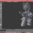
Using the projected curves, throat and mouth sketches, I used the loft feature to create surfaces for each face.
- I had to select projected curves that were next to each other to create a single, flat surface. In the options for loft, you need to choose "Surface" and ensure "New" is highlighted. This creates the first surface of the horn.
- After creating the initial surface, I had to suppress (right click on the new loft) it so I could select one of the previously selected curves.
- The second loft feature required one of the projected curves from the first loft, the reason to suppress it. The main difference with this loft is to select the "Add" option instead of "New." It will create the face but show up red because there is not another face to "Add" too.
- Now you need to repeat step 2 and 3 above until there are four faces.
- Once all the faces have been created, un-suppress them and you should have a single part/surface.
Step 4: Designing the Horn


The Phone Holder
The last thing to do is create another plane and sketch that will go around your phone.
- You may have noticed a random dotted line that connected the mouth to the throat. I used this line to ensure that your phone lays flat on a surface while using the horn.
- The plane is parallel to the same one as the throat and mirrors its dimensions. If the dimensions of the phone change, the throat and phone holder will also change.
- To finish off the phone holder, I made a lofted surface using the throat and phone holder.
Lastly, I needed to create was surfaces to fill the wholes of the Mouth and Throat/Phone Holder. These are essential for exporting.
Step 5: Preparing the Horn for Export


At the moment, the horn is a bunch of surfaces which have zero thickness (not so great for exporting an STL). To export the horn in a format for the next program, it must become a solid body/part.
Again, OnShape came to the rescue with a nifty feature to make this process simple.
- Select the Enclose feature in the submenu of Thicken.
- Choose the surfaces on the bottom left and confirmed with the Green Check button.
This single feature of OnShape reduced the number of steps by like...30(?). I didn't want to figure out the actual number but I think it was magic.
Step 6: Exporting the Horn


Before you can make anything from paper, you need to get your horn from digital to...well...digital. It's just a different form of digital, but it is one step closer to paper.
One last step in OnShape:
- To export your horn from OnShape and into Papakura, right click on "Horn Part" just above the previously mentioned surfaces.
- From the popup menu, choose "Export..."
- Change the "File Name" as desired.
- Choose "STL" in format.
- STL Format should be "Text."
- Units are in "Inch"
- Resolution can be "Coarse", "Medium" or "Fine". As you go from "Coarse" to "Fine," the downloaded file size will increase.
- Leave "Options" as "Download." This will automatically download the file to your computer. You can choose to "Store file in a new tab," but you will have to download it from the tab to use the file.
- Last, of all, click "OK" and the download should start.
Step 7: Horn Variables

I created a bunch of variables to make it easier to adjust different parameters of the horn as needed. Below is a list of each variable used for each sketch. To change the value, double-click on the variable, which opens a box, and selects the "Green Check Mark" to confirm the change.
- Horizontal Profile
- #Phone_Width
- #Mouth_Width
- #Horn_Length
- #Hor_Angle1
- #Hor_Break1
- Vertical Profile
- #Phone_Thickness
- #Phone_Holder_Length
- #Mouth_Height
- #Vert_Angle1
- #Vert_Angle2
- #Vert_Break1
- #Vert_Break2
- Throat
- #Phone_Width
- #Phone_Thickness
- Mouth
- #Mouth_Width
- #Mouth_Height
- Phone Holder
- #Phone_Width
- #Phone_Thickness
Afterthought, the last bit of information that you will need is to know how long your horn profile is. I created two sketches that have measured the lengths of each face of the horn (double-click the sketch to open). Be sure to add each length together to ensure your horn is not any longer than the paper you are using. Though, there are options to have the horn span multiple sheets.
Step 8: Making the Paper Pattern


To make the pattern for the horn, you will need to install Pepakura. This little beauty will do everything we need for free-ninety-nine. The install is pretty quick so drinking a bev while you wait will be short-lived. If you would like to get a little more acquainted with the software before diving into your own project, krsiak created some great tutorials.
Working with Pepakura is intuitive and the icons are easy to understand.
- To start, you will Open the file using the classic "File" icon. Just browse to the location of the downloaded STL file.
- This will cause a pop-up window that asks a few important questions. For example, the first question asks if your STL file is Binary, ASCII or Auto Detect. I'd recommend Auto Detect.
- The prompts from the windows are straightforward and for the most part, you can select "Finish" as soon as possible.
- Ensure the Scale of the model is 1 Unit = 1 in
- Unfold button, uncheck the auto box and double check the scale is correct.
- You can also change the spacing of the parts in this step.
- This will give you a basic unfolded part.
- Now comes the fun, you will need to start manipulating the fold lines to fit all of the pieces on each piece of paper.
- In the top left, there are three buttons you want to use to move the parts around, adjust where the faces separate and where the gluing flaps are.
- The first button to use is "Join/Disjoin Faces". This changes where the faces connect. You will need to rotate your model around(right mouse button) to get all the edges.
- Next, we will change where all of the flaps are located. To do this, select the "Edit Flaps" button, which will open a new window.
- To change flap locations, just hover over the troublesome flap and a red line will appear showing you where it will move too.
- I like to move the faces around to see how I need to "Disjoin" them more to be as efficient with my paper space as possible. The green circle can be used to rotate the faces.
- In the top left, there are three buttons you want to use to move the parts around, adjust where the faces separate and where the gluing flaps are.
- Once everything looks good, I print it as a PDF
- Actually, print the patterns.
- You will not want to print the mouth or throat surfaces as they do nothing.
Step 9: Cutting and Pasting


Now, lets cut to the point and make this horn.
Required tools:
- Scissors or X-Acto
- Glue
- Patience
Assembly Instructions
- Cut pieces out, so they are on individual pieces of paper.
- Cut out each piece precisely.
- Crimp the edges of the folds that span the surfaces and continue to the middle.
- Fold the tabs inwards so they can be glued to the other surfaces.
- There are Two ways to go here:
- Glue the individual faces together.
- Glue the pieces that make up the throat or mouth perimeter.
- Start gluing the rest of the surface pieces together until you complete the horn.
A few pro-tips:
- Tape is easier to use than glue.
- Glue needs some time to set before moving on.
- Using an X-Acto creates cleaner cuts and you can get into the corners easier.
- Take breaks if needed.
Attachments

Step 10: And Now It's Time for the Science!


Doing the Maths
The main maths I was worried about is the cutoff frequency of the horn. This dictates how low of a frequency you will hear come out of your horn. After calculating the cutoff frequency, you can use a frequency/tone generator on either your phone or the internet to have an idea of what to expect.
I am simplifying the use of the equations in this section and if anyone has an idea how to accurately predict the cutoff frequency past my general understanding, please help out.
The two equations are shown in the pictures above and simplified below.
The first equation we will use calculates the horn profile or flare constant.
m = ln(Sl/So)/L
This is more easily read as:
flare constant = natural log(mouth area / throat area) / horn length
Now in terms of phone variables:
flare constant = ln( (#Mouth_Width * #Mouth_Height) / (#Phone_Width * #Phone_Thickness) ) / #Horn_Length
Annoying step: convert all measurements to meters or copy the values from the variable in OnShape
- At this point, I got annoyed with doing the conversion maths and changed the units in OnShape to meters.
Now input the new measurements into the equation:
flare constant = ln((0.2667 * 0.2032) / (.0889 * .019))/.22866 = 15.1682
The second equation is to calculate the cut-off frequency.
fc = (m * c) / (4 * pi)
Simplified:
cut-off freqency = (flare constant * speed of sound) / (4 * 3.141592)
Calculating the cut-off frequency for our horn:
cut-off frequcy = (15.1682 * 344) / (4 * 3.141592) = 415.2243 Hz

Participated in the
Paper Contest 2018

Participated in the
Epilog Challenge 9


