

Introduction: Personal Security System Using Arduino
Here is just a simple guide on how to create your own mini "security system" using an Arduino. This is just a fun project, please don't actually rely on this device to keep your house secure! This design uses an Arduino, a HC-SRO4 Ultrasonic Sensor, a Buzzer, and some LED's. Ultimately from this tutorial, I hope you learn how to use a buzzer and LED's to display how far away an object is from the ultrasonic sensor.
Step 1: Assemble Materials

Materials required are:
(1x) Arduino Uno
(1x) Breadboard
(1x) HC-SRO4 Ultrasonic Sensor
(1x) Buzzer
(1x) Green LED
(1x) Yellow LED
(1x) Red LED
(4x) 220 ohm Resistors
(10x) Jumper wires
Step 2: Setup

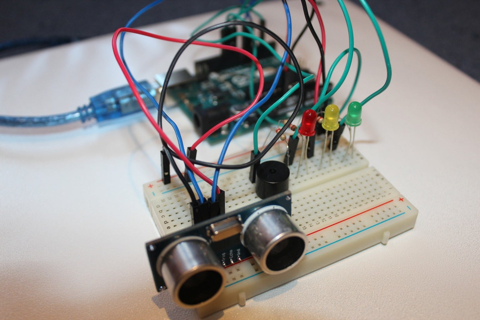
The photo above shows the setup of the project.
The circuit should be setup as follows:
Connect a red wire from the 5V pin on the Arduino to the positive channel of the breadboard.
Connect a black wire from the GND pin on the arduino to the negative channel of the breadboard
Buzzer = pin 3
On Ultrasonic Sensor:
Echo = pin 6
Trig = pin 7
LEDs:
RedLED = pin 9
YellowLED = pin 10
GreenLED = pin 11
The green wires connected to the LEDs should be connected in line to the positive side of the LED, while the negative side of the LED should be connected to the negative channel of the breadboard using a 220 ohm resistor.
Step 3: Assembly - Breadboard

Firstly, let's connect the 5V and GND pin on the Arduino to the breadboard. As I mentioned before, be sure that the wire attached to the 5V pin is connected to the positive channel of the breadboard, and the wire attached to the GND pin is connected to the negative channel of the breadboard.
Step 4: Assembly - Ultrasonic Sensor
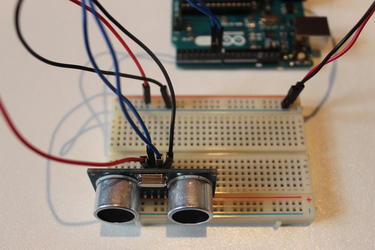
Time to connect the HC-SRO4 ultrasonic sensor! A great tip is to place the ultrasonic sensor as far right to the breadboard as possible and make sure that it is facing out. Referring back to the setup picture, you should connect the GND pin on the ultrasonic sensor to the negative channel on the breadboard. Next connect the Trig pin on the sensor to pin 6 on the Arduino and connect the Echo pin on the sensor to pin 7 on the Arduino. Lastly, connect the VCC pin on the ultrasonic sensor to the positive channel on the breadboard. Refer to the picture above if anything gets confusing.
Step 5: Assembly - LEDs
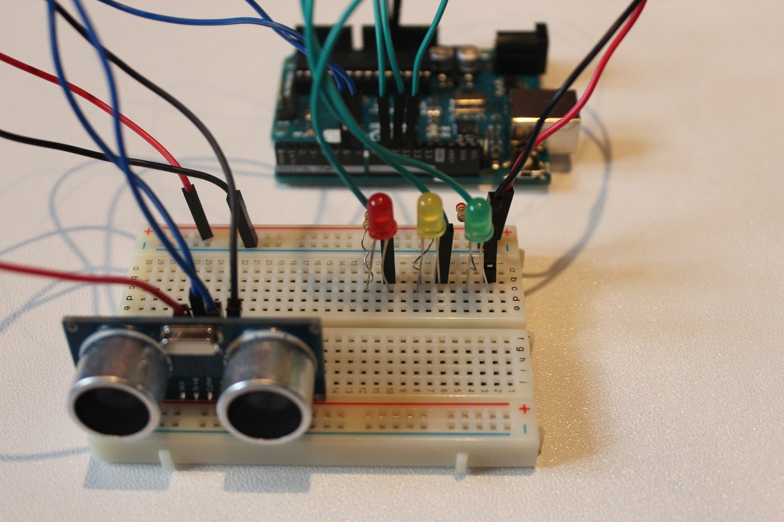
The next step is to connect the LED's to the breadboard and Arduino. If you need to, I highly recommend that you refer back to the setup picture (Step 2), attaching the LEDs is pretty easy, there's a lot of repetition. Let's first attach the Green LED. So the way to do this, is to connect the anode (the longer leg) to pin 11 on the Arduino with a green wire, and to connect the cathode (the shorter leg) to the negative channel on the breadboard, using a 220 ohm resistor. Then repeat that step for the Yellow and then the Red LED, make sure to connect the anode (the longer leg) of the yellow LED to pin 10 on the Arduino and then connect the anode of the red LED to pin 9. Once you have done that, your setup should look similar to the picture above.
*NOTE*
Resistors are not absolutely necessary, however they are highly recommended to be used.
Step 6: Assembly - Buzzer

The last part of the setup for this, is connecting the buzzer to the breadboard and the Arduino. This is one of the easiest parts of the whole setup. All that is required to do is to connect the longer leg of the buzzer to pin 3 of the Arduino using a green wire and then connect the shorter leg of the buzzer to the negative channel of the breadboard using a 220 ohm resistor.
*NOTE*
It is HIGHLY recommended to use a resistor in connecting the shorter leg of the buzzer to the negative channel of the breadboard. This greatly reduces the volume of the buzzer and prevent it from dying to quickly.
Step 7: Code

Now that you have finished the setup, its time to code the Arduino. All you have to do, is to open the Arduino program on your computer and then copy and paste the code from below. Feel free to change the distances at which the ultrasonic sensor detects an object from and the volume of the buzzer!
#define trigPin 6<br>#define echoPin 7
#define GreenLED 11
#define YellowLED 10
#define RedLED 9
#define buzzer 3
int sound = 500;
void setup() {
  Serial.begin (9600);
  pinMode(trigPin, OUTPUT);
  pinMode(echoPin, INPUT);
  pinMode(GreenLED, OUTPUT);
  pinMode(YellowLED, OUTPUT);
  pinMode(RedLED, OUTPUT);
  pinMode(buzzer, OUTPUT);

}
void loop() {
long duration, distance;
digitalWrite(trigPin, LOW);
delayMicroseconds(2);
digitalWrite(trigPin, HIGH);
delayMicroseconds(10);
digitalWrite(trigPin, LOW);
duration = pulseIn(echoPin, HIGH);
distance = (duration/5) / 29.1;
if (distance < 50) {
digitalWrite(GreenLED, HIGH);
}
else {
digitalWrite(GreenLED, LOW);
}
if (distance < 20) {
digitalWrite(YellowLED, HIGH);
}
else {
digitalWrite(YellowLED,LOW);
} if (distance < 5) {
digitalWrite(RedLED, HIGH);
sound = 1000;
}
else {
digitalWrite(RedLED,LOW);
}
if (distance > 5 || distance <= 0){
Serial.println("Out of range");
noTone(buzzer);
}
else {
Serial.print(distance);
Serial.println(" cm");
tone(buzzer, sound);
}
delay(300);
}
Once you've done that, and you've plugged in your Arduino to your computer, run the code and you're finished. If you've followed all the directions properly, the closer your hand or any object gets to the HC-SRO4 ultrasonic sensor, the LEDs should progressively light up until and you're so close that the buzzer will go off.
Step 8: The Working Arduino!
This is a really fun project, I had a lot of fun creating it. I just want to give a shoutout to my Computer Science teacher Mr. Smith for being so very helpful and being amazing!


