

Introduction: Photon Drawing Robot (HTML Canvas)


The robotic artist is a robotic arm that draws out what you draw on an HTML canvas.This project was inspired by the robot found here. I found the robot to be impressive and I wanted to "change it up". I thought making it mimic what you draw on a screen would be an impressive feat, so that is what I did!
Step 1: Materials List

- Photon Board
- Bass Wood 1/8 in. thick
- 4 x SG92R Micro Servos
- 1 x Sharpie marker
- Cutting tools (Hacksaw, X-acto knife, etc.)
- 1 x USB power brick
- USB power cord
- 1 x Breadboard
- Cyanoacrylate glue (Krazy Glue)
- Zip ties
Step 2: Creating the Arms


1. Using the basswood, cut two "arms" out. I chose to cut one arm ~9.5 cm long and the other ~11.5 cm. Both were cut about 1.25 - 1.4 cm wide to accommodate for the width of the servos. If you prefer, you can cut the arms to whatever length you choose, however, you must make one arm a few centimeters longer than the other. Keep in mind the weight of the arm increases as the length increases. If the arm is too heavy, the servos will jitter and constantly reposition themselves.
2. On the top of each arm, cut a slot of about 2 - 3 cm long and about 1 cm wide. This slot will be used to hold in the servo for the arm. This step isn't necessary, but I feel that it cleans up the appearance quite nicely.
3. On the ends opposite of the servos superglue one of the provided arms onto the wood. This will give the servos an attachment point and will allow it to rotate the arm.
4. Cut a square piece of wood of about 4 cm x 4 cm. This piece of wood will serve as the base for the entire robot.
The shorter wooden arm should have both the servo arm piece and the servo on the same side. The longer arm should have the servo arm piece on one side, and the servo on the other side. This is extremely important because it serves to remove the offset introduced by the smaller arm. As seen in the top-down view pic, if this were not done, the origin of rotation would be offset by a few centimeters from the base, and the drawn image would not come out correctly.
*********************************************************
Additional info:
- You can substitute basswood for balsa wood as it is much lighter. I chose not to use balsa wood because I was not sure it would be able to handle the stresses of drawing.
- I chose to shave off wood near the servo arms. It certainly reduced the weight of the arm which in turn mitigated the jittering of the servos.
Step 3: Assembling the Whole Robot


1. The first servo is placed spindle down onto a square base (4 cm x 4 cm). A servo arm should already be glued onto the center of the base.
2. This base can then be glued onto a larger, heavier slab of wood. The servo arms have a lot of torque; gluing the robot to a heavier base prevents it from toppling over when moving.
3. The second servo should be attached onto the side of the main base servo. I used zip-ties to fasten them together. Once that is done, you can attach your smaller arm onto that servo. I used a piece of wood to further tie them together. I screwed both servos onto that piece of wood and cut off the extra. Initially it was going to be used as a counterweight, but it wasn't effective.
4. The third servo should already be attached onto the first arm. You may connect the spindle of the third servo onto the servo arm found on the second arm.
5. The fourth servo will already be attached on the the second arm as well. To attach the writing utensil onto the servo, I put one of the servo arms onto the servo spindle, and I fastened the writing utensil onto it using zip ties.
************************************
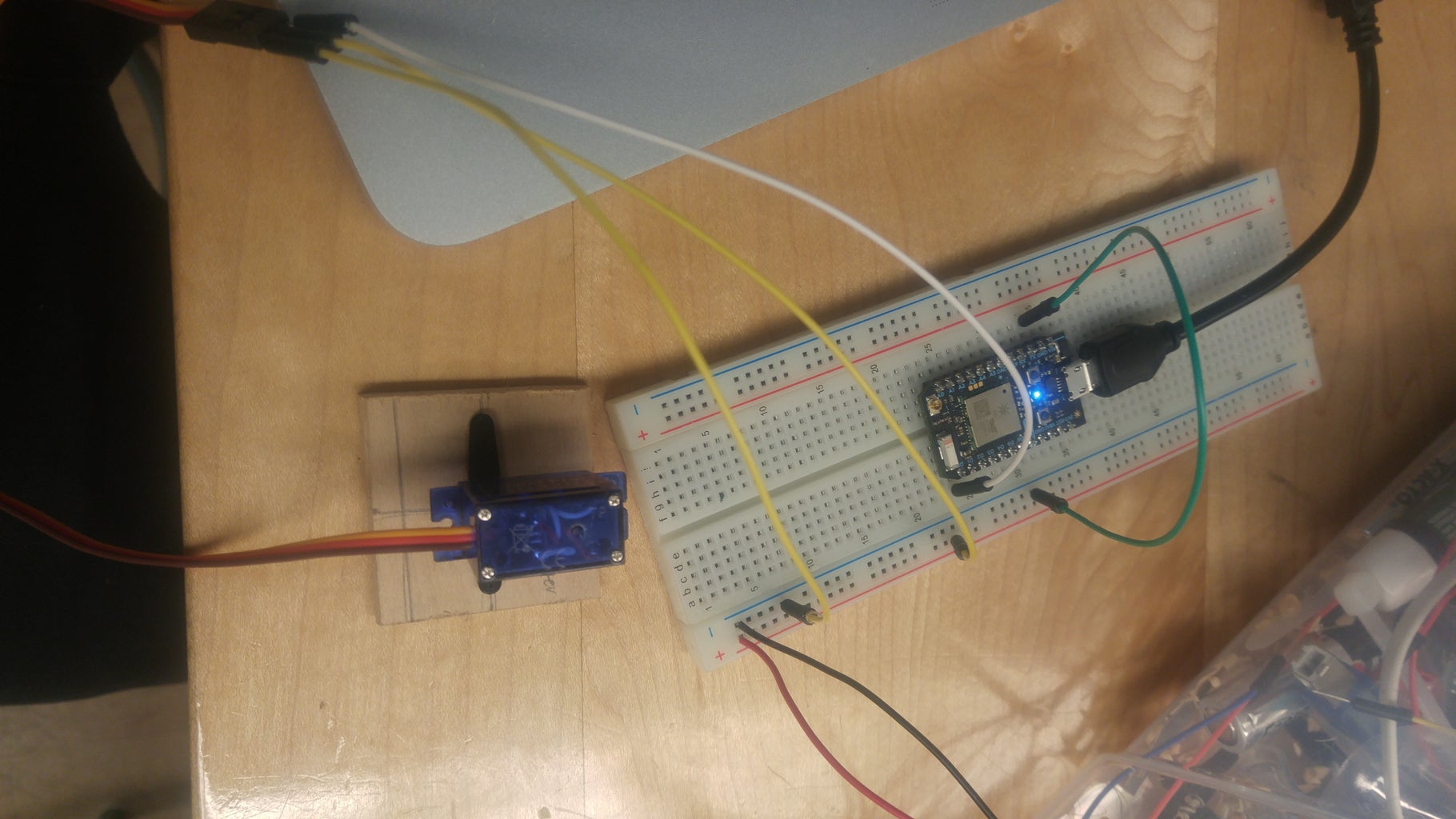
Powering the robot:
To power the robot, I spliced a USB cable, connected the positive and negative terminals onto the breadboard, and connected each servo onto it. I then connected the negative side of the breadboard with the ground of the Particle Photon to create a common ground. A USB power brick was my power source; it provided 5V and roughly 1500 mA of power. You can experiment with higher voltages, but keep in mind that too high of a voltage can burn out the servos.
************************************
Connecting the Servos:
Set up is very simple! The base servo (Servo 1) should be attached to pin D0. The second servo should be attached to pin D1, the third servo to pin D2, and servo 4 to pin D3.
Step 4: Code and a Brief Explanation of How It Works


The HTML, JavaScript, and Arduino code can be found right here. Simply flash the .ino code onto your Particle Photon board, edit the JS file "calculations.js", and use the provided HTML file to get started.
You will need to edit the file and put your device ID and access token where specified in the JS file.
**********************
Positioning of the arm:
The first step in drawing the point is aiming the base servo towards the direction of the point. To find the angle at which the base servo should be pointing towards, we can draw a right triangle connecting the point and the servo together. We can find the length of the base by getting the x coordinate of the point and multiplying it by our 'pixel size ratio' which is the width of your real life canvas (paper) divided by the width of the HTML canvas (px). This converts the point into a real unit we can measure. To find the height of the right triangle, we can do the exact same thing, except this time we use the y coordinate instead. The hypotenuse must also be found because it is essential for the positioning of the arms in the second part. This can simply be done using the Pythagorean theorem. To finally find the angle for the base (shaded red), we can use any of the 6 trigonometric functions to find the angle.
The positioning of the arms so that the drawing tool touches the paper and remains perpendicular in relation to the paper requires some more math. As you can see in the image, by using two triangles and some already provided variables (size of paper, distance of point from robot) we are able to find the angles of the triangles and we can position the arm directly over the point. Most of this simply used the Law of Cosines.
**********************
Disclaimer:
As you can see in the calculations.js file, when all calculations are completed, the values are rounded before being sent to the servos. As a result, the robot arm's drawing will not be entirely accurate. The servos cannot move within a tenth of a degree so any input received by the servos will be integers.
