

Introduction: Pier 9 Resource: DMS Certification Part II: Machining


This Instructable is for Workshop Users at Pier 9. It is a continuation of the DMS Certification Part I: 3D CAM in Fusion 360 Instructable, which teaches you CAM (Computer Aided Manufacturing) for machining a wooden serving spoon, using Fusion 360 and a model that is provided for you. This spoon is the certification part for the DMS 5-axis router, meaning that you must complete this project after taking the DMS Safety/Basic Use course in order to be checked off to use the DMS for your own projects.
Now that you have the G-code for this part on your USB drive, it's time to machine! You'll learn how to prepare and install your stock, insert and measure tools, establish a WCS (Work Coordinate System), and load and run programs on the DMS router.
After following these steps, you'll have a functional spoon to take home, as well as serious programming chops.
At Pier 9, make sure that you have taken the following courses:
Step 1: Milling, Cutting, and Measuring Stock Material


1) In Setup 1, recall that you chose a Fixed Size Box of 20" x 3.5" x 1.5". You will cut your stock to this size.
Later on, when you're making your own parts for the DMS, it's recommended that you prepare your physical stock before doing CAM in Fusion 360. Measure your actual stock, and design your model and stock sizes accordingly.
2) If you're starting with raw hardwood--in these pictures, you'll see poplar--use a joiner and planar to get the edges square and the piece milled to a thickness (height) of 1.5".
3) On the table saw, cut your piece 3.5" wide.
4) Finally, move to the compound miter saw (chop saw) to cut your piece to a length of 20". If you have enough material, cut two pieces. It never hurts to have extra stock.
5) Use calipers to measure your actual stock size.
6) Update Setup 1 and Setup 2 in your CAM program with actual dimensions. Don't change any other parameters.
7) Follow steps 34 and 35 in the DMS Certification Part I Instructable to generate setup sheets and post process G-code to your USB drive.
Step 2: Preparing Stock


1) Draw a line exactly 0.75" from the two edges of the stock (along the 20" length).
You will use this line to determine where your screws will go into the material. Use the Inspect tool (hot key i) in Fusion 360 to confirm that the holes in both sides of the rectangular prisms on either side of your spoon are 1.25" from the outer edges. In this way you can ensure that the drill bit will be 0.5" from your screws, preventing a collision.
If you are ever worried that a tool will come in contact with one of your workholding screws, use a brass screw instead of a drywall screw. There are some in the DMS workholding drawer.
2) Find four 2" drywall screws, or wood screws between 2" and 2.25".
3) Choose a drill bit that is slightly larger than the threads of the screw.
You will be drilling through-holes in your material, so that the drywall screws are only digging into the spoiler board below. This is the proper way to cinch two materials together. Surprisingly few people know this.
4) Put your stock in a vice, or clamp it down, and drill four holes on your two drawn lines. Ensure that the holes aren't too close to the edge of the material.
5) Make sure the screws can slip through these through-holes without aid of a drill or screwdriver.
Step 3: Installing Stock in the DMS


1) Choose a spoiler board with a thickness of at least 0.75" from behind the DMS, or cut one to size in the wood shop. Remember the area of the DMS machine bed is 5' x 5', so ensure that your spoiler board is over 4.5' in one direction.
2) Select four C-clamps from the wood shop.
3) Align the front edge of the spoiler board with the slot or channel in the acrylic machine bed, and then clamp the spoiler board down.
You will need to crawl into the machine and reach down to get enough clamping force to do this properly. If the machine is on, activate the E-stop.
4) Draw a 20" line about 3-4" from the front edge of the spoiler board.
5) Align the front edge of your stock to that line, and then use an impact driver or drill to screw it down into place.
In Fusion 360, check Setup 1 to confirm that your stock is oriented correctly. You placed the Work Coordinate System (WCS) in the upper left corner of the stock, with X along the 20" length, Y along the 3.5" depth, and Z along the 1.5" height. Your stock is placed correctly in the machine.
6) Using calipers, double check that your spoiler board is over 0.75" in thickness.
If your spoiler board is too thin, your 1/2" drill bit will go into the acrylic bed. You programmed the drill to go a total of 0.5" below the stock bottom--see Step 24, #9 in the DMS Certification Part I Instructable to review this. Notice in the image that you can easily measure the thickness of a material by placing the caliper upside down, putting the bottom of the caliper on your bottom surface (acrylic), and then sliding the back jaw down until it rests on the part you're measuring (plywood spoiler board). This distance is the same as the distance between the jaws.
7) Set up your laptop on top of the DMS tool library Lista, alongside your USB Drive, printed setup sheets, and DMS Safety/Basic Use handout. You will periodically check your CAM Simulation as you machine.
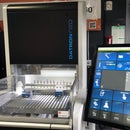
Step 4: Power on and Reference Search


1) Following the DMS Safety and Basic Use Handout, Power on Machine and perform the Reference Search (page 4).
2) Select a 1/2" drill from the CNC Only Drills drawer in the CNC shop, to the left of the Haas Tool Library.
3) Insert this custom tool into a holder with a 1/2" collet (page 5). You will find extra holders and collets behind the library tools.
Step 5: Inserting and Measuring Tools


1) Referencing Setup Sheet 1, insert tools 1-4 into the DMS and measure them (page 7).
Remember that the chronological tool numbers in your program do not correspond to the numbers in the DMS tool library drawer. For instance, Tool 1 (T1) in this program is the 1" Rough Short End Mill, which is labeled #34 in the DMS library. You will see the DMS library number in the comment for each tool in the Setup Sheet. This number is affixed to the upper right hand corner of that tool's spot in the DMS Tool Library drawer, and is also laser etched on the tool holder. Check that the laser etched number is correct, as sometimes users put tools back in the incorrect spot.
2) Referencing Setup Sheet 2, insert Tool 5 (T5, 12mm EM Long) into the DMS and measure it (page 7).
3) When you are finished, tools 1-4 should be in slots 1-4 in the DMS magazine at the back of the machine, with T5 in the spindle.
Step 6: Establish Work Offset


1) Perform a tool change to bring Tool 4 (1/2" drill) into the spindle.
If you have a drill in your program, it's very useful to use it to establish your Work Coordinate System (WCS). This is because drill bits come to a point, as opposed to end mills. You can more easily visually ensure that the drill is in the correct location.
2) Jog the tool's tip to the exact back left corner of your stock--the location where you placed the WCS during Setup 1.
Check from the front and side that the tool is in the right position. Switch to incremental mode while jogging as you get close to the right spot.
If you prefer to set X and Y first, and then jog the tool over the top of your stock and use the "paper method" to set Z, this is fine too. In this case, you will position the tool to the correct X and Y location, and go through steps 1- 13 in the DMS handout. Then, you will jog the tool over your stock, switch to incremental mode, and slowly lower the tool over a sheet of paper on the stock until the paper is lightly trapped. Then follow steps 14-28 in the handout.
3) Set the WCS by following steps 1-28 in the DMS Handout (pages 8-9).
4) Toggle back to the Machine Coordinate System (G53) coordinates by typing G53 and then pressing Cycle Start.
5) Take a picture of the Machine Coordinate System (G53) on the controller. This will be useful if you need to get back to this location at another time.
5) Go back to the WCS (G54) by typing G54 and then pressing Cycle Start. The coordinates should go back to zero.
Step 7: Prepare for Machining


1) Warm up Spindle (page 10).
2) Prepare Spindle Dust Collector (page 10).
3) Load your program (page 11).
Double check that your files are named 100001.PIM and 100002.PIM. If your files aren't six digits, the DMS won't detect them.
Step 8: Run Setup 1: Adaptive and 2D Pocket


1) Before you start machining, double check the simulation of Setup 1.
In particular, look at where the tool enters material in the first toolpath. In your first toolpath, the tool descends above the back left corner, and then sweeps to the right. When you begin machining, the DMS will select T1 from the magazine, start the spindle near Machine Home, jog to the X-Y location above that back left corner of your stock, and then descend. If it doesn't descend in that location, you know your WCS has not been set properly.
1) Execute Program 100001 from Setup 1 (page 11).
As stated in the handout, ensure that the Feed Rate Override switch is set to zero before you hit cycle start, and then slowly increase the Feed Rate to 100%. The correct stance while machining on the DMS is to have a hand on the Feed Rate Override Switch or on the E-stop, while looking through the window on the door. If anything goes wrong, you can also press the red Feed Hold button and then the gray Reset button (see Dry Run, page 11).
3) The Adaptive toolpath should take about twenty minutes to run, and the next 2D Pocket toolpath should take less than a minute.
Step 9: Run Setup 1: Parallel, Contour, and Drilling


1) Tool 3 (1/2" Ball EM Long), will descend in the front right corner of the part--in the front of the scoop of the spoon. This operation will take about ten minutes to run.
At the end of this operation, look at the side of the spoon. Notice that it has marks from this toolpath that match the ones in the simulation. This is testimony to how accurate simulation is.
2) The Contour toolpath, used to clean up those edges, will take about eight minutes to run.
3) The Drilling toolpath will only take a few minutes.
Carefully watch your stock and spoiler board and make sure that the force of drilling isn't pulling the spoiler board up, off of the machine table. If it is, hit Feed Hold and Reset to stop your program and spindle. Turn the key to Setup Mode, pull the E-stop, and place a toe clamp close to the front center edge of your spoiler board. Then, post process just the Drill1 toolpath--Deep Drilling.
Don't ever be afraid to stop the machine and make changes inside the machine, or edit the toolpath parameters. It's easy to post process a toolpath again by selecting just that toolpath or a group of toolpaths, and then loading the new program. In other words, you don't have to post process an entire Setup at a time. Because you haven't moved the part, you can just go ahead and run the new program without worrying about setting a new WCS. This is also a reason to get in the habit of measuring and inspecting a part once you're done machining BEFORE you move it.
Step 10: Flip the Stock


1) When Setup 1 is finished, turn the key to Setup Mode, open the doors, and pull the E-stop.
2) Use the impact driver to remove the part from the spoiler board, and sweep the chips away.
3) Use the air hose behind the back of the DMS to clear the chips out of the holes in the spoiler board.
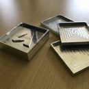
4) Choose three 1/2" compressed dowels from the wood shop (in one of the drawers under the Compound Miter saw).
5) Slide the dowels into the holes--there should be some resistance--and knock them with a rubber mallet until they protrude on both sides.
6) Flip the part away from you, like you did in the CAM software, and align the dowels with the holes. Knock the dowels with a mallet into the spoiler board. Then knock the part down flush against the spoiler board.
7) Use the same four drywall screws to screw the part back down.
Step 11: Setup 2: Two Adaptive Operations and Parallel Finishing


1) Remember that your dowels have ensured that your part is in the correct orientation in the X-Y positions. You also have not machined any of the material on the two rectangular prisms on either side of your stock, meaning that the height of your part has not changed. This means that you do not need to set a new WCS for Setup 2!
In other instances, you might face your part or do something else to change its height. In those cases, it is important that you reset the Z-coordinate of your WCS for Setup 2 by following steps 14-28 on Page 9. This is assuming that your X and Y locations are correctly registered and do not need to be reset. If you don't have a registration system, anytime you move the part you need to reset the X, Y, and Z coordinates of the WCS.
2) Load and Execute Program 100002.PIM.
Again, look at the CAM Simulation to verify where the tool will enter the material. In this case, it will helix ramp into the handle of the spoon. If the tool doesn't descend in this location, stop the the program and check your WCS and CAM simulation.
3) The two roughing operations will take about thirty minutes to complete. Though you don't have as much material to remove, you decreased your optimal load to account for the fact that the part is only being held in position with two small tabs. It is therefore prone to chatter, or excess vibration, which you will hear. You'll also see that the second roughing operation is a bit inefficient, but it's important to remove that excess material around the backside of the spoon scoop to prepare the part for the finishing operation.
4) The Parallel finishing operation will take about ten minutes to complete.
5) When Setup 2 is done, turn the key to Setup Mode, open the doors, pull the E-stop, and remove your part. Congratulations! The machining part is done!
Step 12: Clean Up DMS and Remove Tabs


1) Follow Page 12 of the handout to clean up the DMS and run the Goodnight program. Store the spoiler board behind the DMS.
2) Bring your part into the woodshop, and place the miter on the vertical bandsaw.
3) Take a scrap piece of rectangular stock and place it in front of the miter, so that the front rectangular prism of the spoon is resting against it.
4) Clamp the scrap to the rectangular prism on the spoon.
5) With one hand on the scrap and miter and the other on the spoon, cut through the tab. Repeat on the other side.
5) Clean up the tabs roughly with the spindle sander, and then use sandpaper and finish them up by hand.
Step 13: Finish Spoon


To prepare the spoon for use, apply a food-safe finish to its surface. This could include mineral oil, shellac, or carnauba wax. Click here to read more about food-safe finishes for woodworking projects.
Congratulations! You have a functional serving spoon--but more than that, you have the foundation for a whole new skill set.
As soon as you can, apply your new 3D CAM and machining skills to your own project on the DMS.
Be safe, take your time, and have fun!


