

Introduction: Portable 5V Regulator


I made this 5V Portable Voltage regulator to be part of my Palm Arduino Kit.
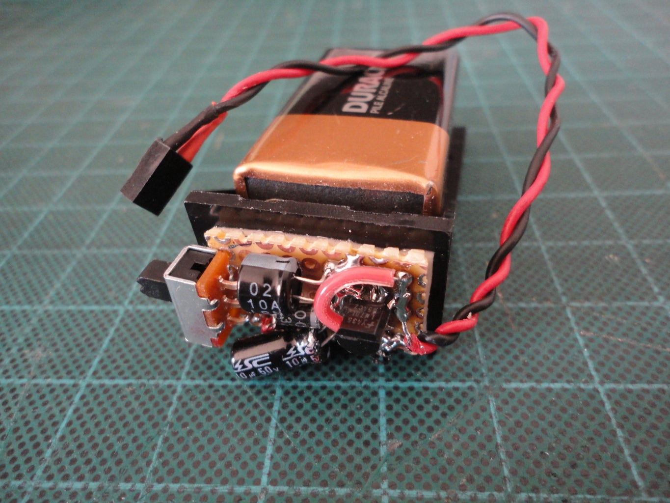
I placed the circuit right on the 9V Battery holder with double sided foam tape.
The circuit was one side circuit.
I placed the components on the solder side of PCB board, because I wanted to use the component side of the PCB to stick to the foam tape and place it right on the top of the 9V battery holder.
The 5V Portable Voltage regulator consists of
Slide switch
1N4001 Diode
100uF Electrolytic capacitor
10uF Electrolytic capacitor
78L05 Voltage Regulator with TO-92 package
and 2-pin Female socket with hookup wire
PCB about 5/8" wide x 1" long.
The schematic of this 5V Voltage regulator is from my notebook when I started to learn embedded electronics. As when I first learned why the diode was added. Because it blocks current from flowing in the opposite direction. And it will block current from flowing backward and damaging the system if you accidentally hook up the power supply the wrong direction.
To built this Portable 5V Regulator is quite easy.
Just solder the components according to the schematics.
And be careful about the polarity of the the diode, and capacitors.
For the 78L05 IC also need to be careful on the pins connectivity.
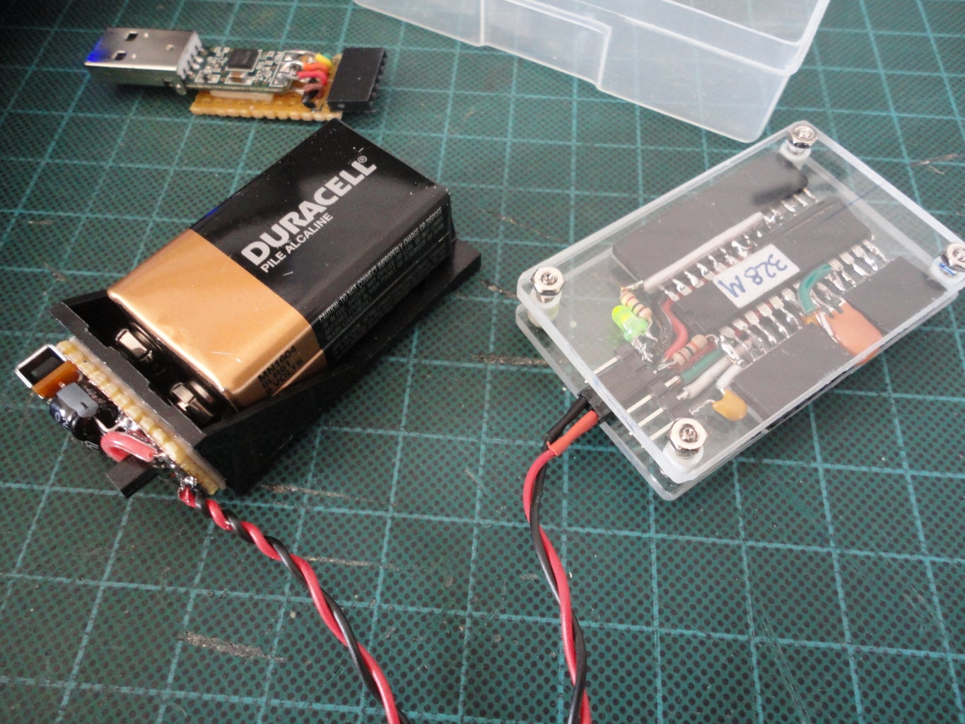
I used 2-pin female socket as the power connector.
NOTE: Thanks to bamfieldjames for an excellent question regarding the LED indicator. So I revised the schematic (as shown), by adding a LED indicator. The dotted connection near 5V output is an option if it is not feasible make a connection at the switch.

First Prize in the
Electronics Tips and Tricks

Participated in the
Pocket-Sized Contest


