

Introduction: PosterBot: Make a Marker-Writing Robot Out of an Old Inket Printer and an IRobot Create


This robot will draw out any small monochrome bitmap onto poster paper. It can mark out the individual pixels just as a printer might. It works best with strings of characters.
This is a moderately difficult project which requires about $50 in parts and basic electronic skills (This doesn't include an iRobot create,Command Module and old Inkjet printer) . You should be able to read a schematic and make a basic prototype or bread board. Some familiarity with C or C++ is handy too.
I recommend that you read through the entire Instructable before beginning your project. It's important that you get the bigger picture because the process will vary depending on your materials.
Parts List:
An Old inkjet printer
An iRobot Create and Command module
Electronic prototype board or bread board
Several rubber bands
Two 9-pin serial cables with at least one male end
4 PC-Mount DPDT 5v DC relays rated at least 1A
4 2n222 transistors
4 1k 1/4 watt resistors
4 diodes
some wire to make jumpers with (unbraided)
~3' of 1/8" Bass wood
Poster marker
Butcher paper (get at least 20')
Voltage regulators (values vary)
White acrylic paint (optional)
Tools:
Hack saw
Epoxy
Box Cutter or Exacto knife
Drill and bit set
Soldering iron/solder
Hot melt glue gun
Multi-meter
Step 1: Get the Parts From the Printer


You need two parts from the printer: the carriage and the paper advancer
The carriage is what the ink cartridges slide back and forth on. It's a metal rack with a motor, a belt, a plastic strip, a white ribbon cable and the actual print-carriage (usually black) where the ink cartridges sit.
You can go ahead and remove the white ribbon, the ink cartridges and the clear plastic strip with the black marks.
The paper advancer is a little harder to remove. It's usually deep in the printer and is attached to a lot of other things.
From the advancer, the parts we want are: the motor, its gear train, its axle (with the little foam wheels) and any bearings it has.
Try to keep these parts in working condition.
We're going to cut the paper advancer axle with a hack saw just outside the second bearing. This will be our medium lowerer which is a not-too-fancy way of saying it the thing that is going to move the marker to and from the paper.
Step 2: Making the Control Board and Configuring the Serial Cables


Here we're going to make the control board. This board will control turn both motors on and off and control their directions with signals from the command module.
The ports will be as follows:
PC5 (top center pin 1) - motor 1(carriage) on/off
PC1 (top center pin 2) - motor 1(carriage) direction
PC4 (cargo bay pin 1) - motor 2 (maker) on/off
PC0 (cargo bay pin 2) - motor 2 (marker) direction
Top center pin 7 - motor 1 supply
Cargo bay pin 7 - motor 2 supply
Top center pin 4 - +5v
Cargo bay pin 5 - grnd
You'll need to strip the serial cables and use the multi-meter to determine which colors go with which pins. Remember: Pin 1 is the top left pin on the female command module.. this means it will be the top right pin on the male serial cable
To make the control board you will need the PC prototype board, the relays, diodes, transistors, resistors and jumpers.
4 PC-Mount DPST 5v DC relays rated at least 1A
4 2N222 Transistors
4 1k 1/4 watt Resistors
4 1N4003 Diodes
RadioShack usually won't have everything. Look for a local electronic supply store or try
DIgikey
or
JameCo
Mount and wire the components according the schematic. I got this schematic from Robot Builders Bonanza 2nd edition
I guess there is a third edition now, but I'm not familiar with it. I highly recommend the book for anyone looking to continue building robots.
This next bit is going to sound like obvious advice but, remember that you want the leads of the components going through to the copper side. I made the mistake of setting up almost the entire board before realizing it was upside-down.
The colored cables you see running away in the photos are the serial cables that correspond to the various pins. I used hot melt glue to attach them to the board to lessen the strain on the solder joint.
I've added picture of my board so you can get an idea how to add them
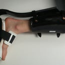
Step 3: Make the Marker Lowerer


In order to make the marker lowerer, you'll need to remove the black print-carriage from the larger structure as seen in the picture showing the separate components. You will need to unscrew the screws that fasten it to the belt. You will also need slide out the metal rod so that the plastic piece can come out.
You'll then want to attach the paper advancer to this black print-carriage piece. Keep in mind the orientation of the future marker and the need for the carriage to slide without impediment.
I used epoxy to attach the bearings to the carriage. I found that Hot-melt Glue is handy to use to keep the parts in place while the epoxy cures. By attaching a piece of wood (bass), you can create a platform so that the marker can be rubber banded on and replaced easily. The small perpendicular piece allows the epoxy to have a greater surface area against the metal.
After this is done, reassemble the complete carriage.
I suggest that you add a foam block or some other stopping device that will stop the marker at it's vertical position. Also, a smaller rubber band to help the marker return to it's neutral position is helpful.
While you're welcome to experiment with different mediums, the best one I found was the fumeless poster paint marker; it's surprisingly long lasting. You should be able to buy both the bass wood and the marker at your local craft store
Step 4: Adding the Carriage to the Robot at Large


This step, of all of them, will be the one that will vary the most from what I'll outline here. Every print carriage is different, and depending how you attached your marker lowerer, you may need to mount it in an entirely different way.
So with that in mind, let me show you how I mounted my carriage.
First, I cut the bass wood in a way that would let me attach it to the cargo bay. I epoxied the pieces together and added paper to help strengthen the joint.
Next, I drilled holes in the wood that lined up with the holes on the cargo bay. I was able to screw down the wood pretty securely
This next step gets a little fuzzy: I added balsa wood extenders and smaller pieces to take some of the stress. It just so happened that my print carriage was just high enough that I was able to raise it an 1/8th of an inch (by cutting the extender and reattaching it to the top of itself) in order to get the marker in just about the perfect marking position. You can trim this position by moving the rubber bands that hold the marker.
I also painted all the wood white. It was amazing how a little paint made the robot look so much better.
You'll also need to run wires out from the control board to the motors. I recommend taking the extra wires from your serial cables and using them. I used hot-melt glue to attach them at the right points to keep them from getting tangled.
Step 5: Calibrating Your Robot


Connect the serial cables (one to the top center, and the other to the cargo bay port) and reattach the wood leaving the PC board in the cargo bay.
One of the first things you'll need to calibrate are the two control motors. The output from the command module is 20V, this is likely far too much for the motors. You can add voltage regulators to limit this voltage to a level that is safe for the motors.
20V is far too much for most DC motors. You'll need to test them at other voltages to figure out where they work best.
I used old RC car battery chargers to supply the voltage to test the motors with. I found out that my Carriage motor worked well at 12V and that the marker motor worked at 6V. So I just bought a couple voltage regulators rated at those voltages and 1A. You want to wire these in series with the motors (that is, in the middle of one the wires running to the robot). If these regulators have a ground pin, it might be a good idea to run up an extra wire from the ground on the PC board.
If you haven't already installed all of your iRobot software including Programer's Notepad and the virtual serial port do so now. Instructions are available in the documentation (which is completely available online here)
Follow the instructions in the Command Module in the "your first project section". Add the Printer.c file as the main file for the code. Be sure to modify the "target =" in the makefile. it should read "TARGET = printer"
Connect the serial cables (one to the top center, and the other to the cargo bay port) and reattach the wood leaving the PC board in the cargo bay.
You'll also want to modify the wait values on the program "printer.c". Namely, you'll want to trim the wait times in the "car" and "mark" function. These will vary with the differing sizes and speeds of your motors. You'll want to trim them so that the marks overlap slightly and are plenty heavy.
Follow the instructions in the manual to compile, download and start the program on the robot (my tip: if it's not working push the reset button).
You made need to spend a fair amount of time calibrating the robot. Pictured below is one of my many test papers.
When everything is trimmed right, the robot should work like this:

Step 6: Creating and Adding Your Own Bitmaps


Finally you have a working robot; but you want it to write other things besides "Instructables.com".
Well here's how you do it.
First you need to create a monochrome bitmap in MSPaint. After opening paint, Click on "attributes" in the image menu. Set the measurements to pixels and set the specs to (for now) 162 wide by 70 high. Fill in the bullet point next to black and white. When you click "OK" you'll get a threatening warning telling you you're about to lose all the colors in your drawing. Click continue.
Create a text box and open the "text toolbar" set your font size to 12pt and select what font you want.
Go ahead and type your string out, and make the box longer if you need to.
When you're finished, select the text and move it to the top left corner of the white area.
Drag the corner of the white space up so it's pretty close to the text.
Now go to the view menu, move the cursor over the "zoom" and select custom. Choose 800%.
You can now resize the white area to 16 pixels tall.
Save the bitmap as a "monochrome" bitmap. (on the dropdown menu)
Next we have to convert the bitmap to a "c" array.
Use the "Fntcvtr" application to convert your bitmap (directions available here)
This program outputs data in a "char" array, we need this to be an Unsigned 8-bit array. To convert it
open the ".out" file in Programmer's notebook.
Select "replace" on the edit menu (CTRL-R).
In the "find what:" box, enter '\ (apostrophe backslash)
Set the replace to "0" (zero)
Click replace all
Run another replace sequence to replace ' (apostrophe) with nothing (empty)
Replace all again.
The purple characters should now be blue.
We now need to redefine the array. Manually replace "Char" with "uint8_t" (it won't turn blue).
Now just copy and past the entire array (including green specs) over the old one in Printer.c.
Be sure to modify the constants "rows" and "col" to the new values of the bitmap.
Compile, load and run. Your set.
Attachments
Step 7: Share What You Draw


I'll post them here on the Instructable.
Thanks and Good luck.
Here's a video of PosterBot drawing "School Starts" in 5x Speed. The funny things at the beginning and end are a schoolhouse and bell, respectively.
Participated in the
The Instructables Book Contest


