

Introduction: Propagator Thermostat Using ESP8266/NodeMCU and Blynk


I recently bought a heated propagator, which should help to get my flower and vegetable seeds germinating earlier in the season. It came without a thermostat. And because thermostats are quite expensive, I decided to make my own. As I wanted to use this opportunity to play around a bit with Blynk, I based my thermostat on a ESP8266/NodeMCU development board that I had lying around.
For previous projects, I used sites like instructables.com a lot for inspiration and help whenever I got stuck. No more than fair to make a small contribution myself, so here is my first instructable ever!
Disclaimer: This project works on AC 230V which is quite dangerous and anything wrong may kill you. I cannot be held responsible for any damages, injuries or loss of life. Make this at your own risk!
Step 1: List of Things I Used


2 DS18B20 1-wire temperature sensor
1 158x90x60 case with clear cover
1 5V USB phone charger
1 Short USB 2.0 A Male to B Male Micro 5 Pin Data Cable
1 4.7kΩ Resistor
1 waterproof plywood block, about 10x5x2cm
1 piece of white plastic tube, diameter 12mm, length 16cm
1 230V power cable with plug
1 230V female power socket (2 pins)
1 230V female power socket (3 pins)
1 6 position 2 row terminal block
1 stereo audio cable with 3.5mm stereo jack plug at one end
1 piece of white perspex about 160x90
And some connection wires, heat shrink tubing, glue, double sided adhesive tape, black spray paint, PCB board standoff spacers, M3 bolts and 1.5mm/6.5mm/12mm/16mm drill
Step 2: Designing the Thermostat

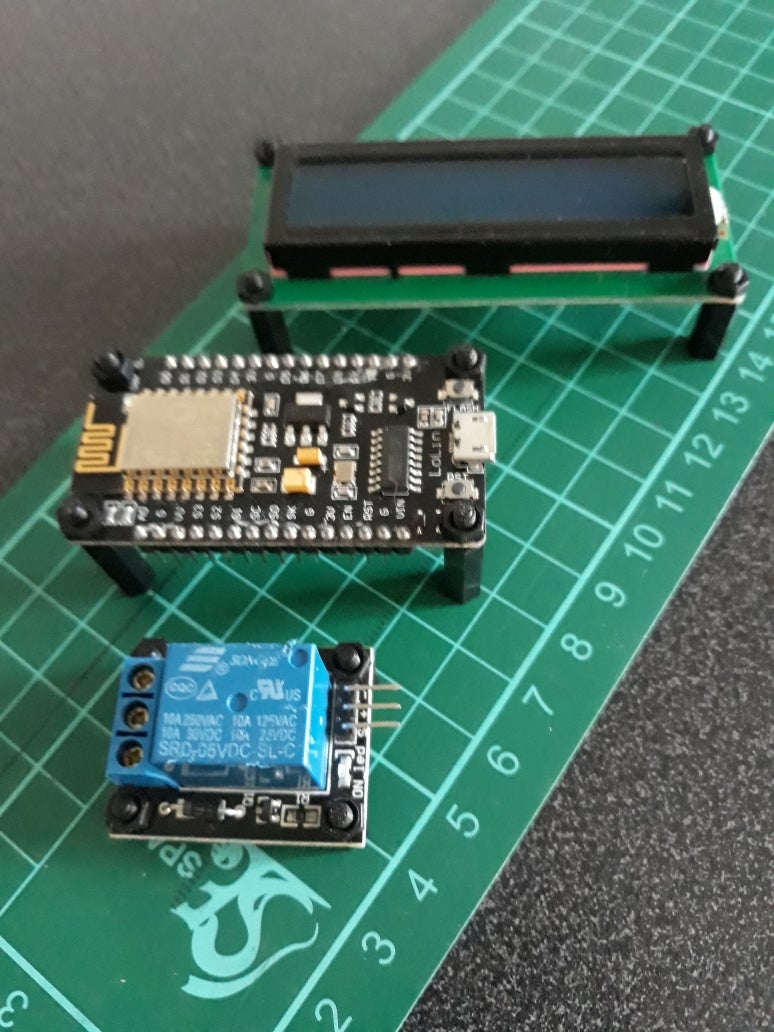
As said, the thermostat is build up around a ESP8266/NodeMCU development board.
The actual temperature of both the soil and the air in the propagator will be measured by 2 temperature sensors. These sensors have a so-called 1-Wire interface, which means that they can be connected in parallel to one input port. As mentioned in this excellent datasheet the 1-Wire bus requires an external pullup resistor of approximately 5kΩ. I use a 4.7kΩ resistor between the sensors signal line and the 3.3V of the NodeMCU.
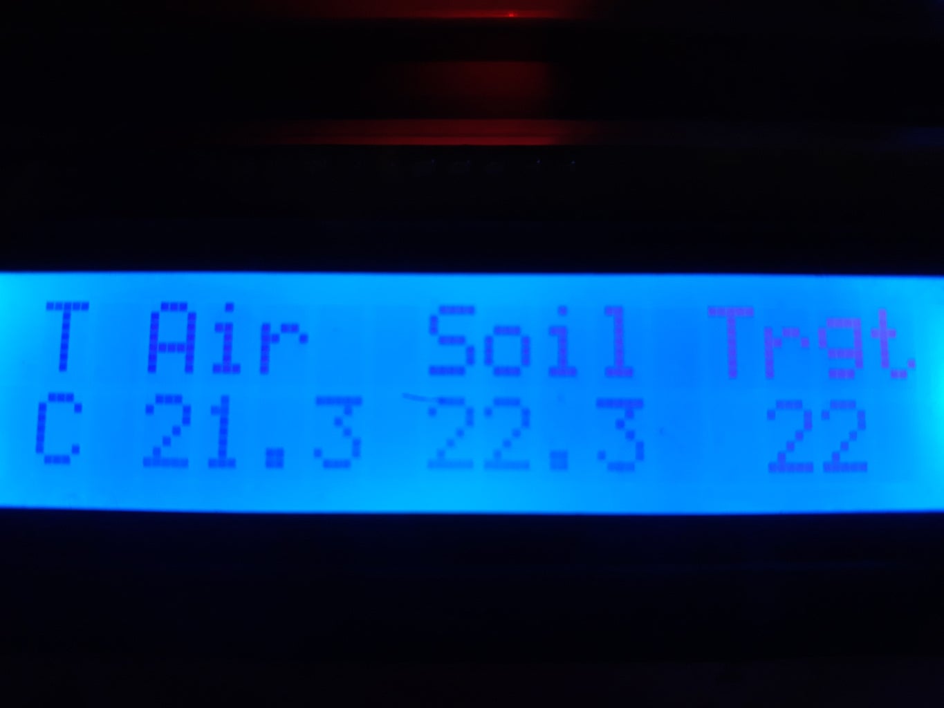
To be able to increase or decrease the desired target soil temperature, 2 pushbuttons are added, as well as a 16x2 character LCD screen to provide some feedback on the current and target temperatures. This LCD screen has a built-in backlight. To prevent the backlight from being on all the time, I decided to add some code to dim the screen after some time. To be able to activate the backlight again, I added another pushbutton. Finally, a relay module is added to switch the power to the heat cable in the propagator on and off.
The picture above shows how these components are connected to the main unit.
Step 3: Making the Thermostat 'Blynk'


Because we need some data from the Blynk app in our code later on, let's first take care of the Blynk business.
Follow the first 3 step of the Blynk getting started instructions.
Now create a new project in the Blynk app. As project name I chose 'Propagator'. From the device list, select 'NodeMCU', connection type is 'WiFi'. I like the dark theme, so I chose 'Dark'. After pressing OK, a popup will be shown stating that an Auth Token was sent to your email address. Check your mail and write down this token, we need in the NodeMCU code later on.
Tap on the empty screen that is now shown and add:
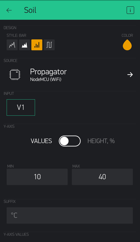
- 2 gauges (300 energy each, so 600 in total)
- 1 SuperChart (900 energy)
- 1 Value Display (200 energy)
- 1 Slider (200 energy)
- 1 LED (100 energy)
This exactly consumes your free 2000 energy balance ;-)
The pictures above show how to layout the screen with these elements. By tapping each element, the detailed settings can be adjusted (also shown in the pictures above).
Once done, activate your project by selecting the 'play' button. The app will (of course) fail to connect, because there is nothing yet to connect to. So let's move on to the next step.
Step 4: The Code That Makes It All Work
Now it's time to program our ESP8266/NodeMCU. I use the Arduino IDE application for this, which can be downloaded here. To set it up for the ESP8266/NodeMCU, have a look at this great instructable by Magesh Jayakumar.
The code I created for my Propagator Thermostat can be found in the Thermostat.ino file below.
If you want to re-use this code, make sure you update your WiFi SSID, password and your Blynk Authorization token in the code.
Attachments

Step 5: Constructing the Temperature Sensor Module

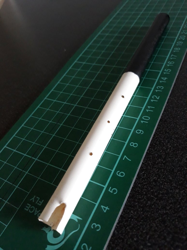


The base of the propagator will be filled with a layer of sharp sand or very fine grit of about 2cm thick. This will spread the bottom heat more evenly. To properly measure the 'soil' temperature, I decided to go for the waterproof DS18B20 temperature sensor. Although my propagator came with an onboard analog thermometer to measure the temperature of the air inside, I decided to add another temperature sensor to measure the air temperature electronically as well.
To hold both sensors nicely in place, I created a simple wooden structure. I took a piece of waterproof plywood and drilled a 6.5mm hole from side to side to hold the soil temperature sensor, leading the sensor wire through the block. Next to that I drilled a 12mm hole in the centre of the plywood block, to about 3/4 of the total height, and a 6.5mm hole from the side, halfway through the block, ending in the 12mm hole. This hole holds the air temperature sensor.
The air temperature sensor is covered by a plastic white tube that fits inside the 12mm hole. The length of the tube is about 16cm. The tube has several 1.5mm holes drilled in the bottom half (where the sensor is), the top half is painted black. Idea is that the air in the black part of the tube heats up a bit, rises to the top and escapes, thus creating a flow of air around the sensor. Hopefully this leads to a better reading of the air temperature. Finally, to avoid the sand or grit from entering, the holes for the sensor cables are filled with glue.
To connect the sensors, I used an old stereo audio cable that has a stereo 3.5mm jack plug at one end. I cut off the connectors at the other side and soldered the 3 wires (my audio cable has a copper ground, red and white wire):
- both black wires from the sensors (ground) go to the ground wire of the audio cable
- both red wires (+) go to the red wire
- both yellow wires (signal) go to the white wire
I isolated the soldered parts individually with some heat shrink tubing. Also used some heat shrink tubing to keep the 2 sensor wires together.
The completed Temperature Sensor module is shown in the 4th picture above.
After completion of the Temperature Sensor module, it is installed in the center of the heated propagator using some double-sided adhesive tape. The wire is fed through the existing opening (which I had to enlarge a bit to make the wire fit) in the propagator base.
Step 6: Constructing the Thermostat Module


The ESP8266/NodeMCU, the display, the relay and the 5V power supply neatly fit into the 158x90x60 mm case with transparent cover.
I needed a baseplate to mount the NodeMCU, LCD display and relay inside the case. I thought about ordering a 3D printed baseplate, so I created a .stl file in SketchUp. I changed my mind and simply made it myself from a piece of 4mm white perspex. Using SketchUp, I created a template to mark the exact place for the 3mm holes to drill. See the .skp file for an example. The components are mounted on the baseplate using some standoff spacers of the appropriate length.
I drilled the holes for the buttons and connectors in the sides of the case, installed the buttons and connectors and wired them up using different colored wires to avoid any wrong connections. I carefully wired up the 230V AC parts. Again: 230V AC can be dangerous, make sure you know what you're doing when preparing this part of the project!
The 5V power supply and terminal block are kept in place on the bottom of the case with some double sided adhesive tape.
After connecting the wires to the NodeMCU, it took some fiddling around to fix the baseplate in the case with some m3 bolts.
Final action: put the transparent cover in place, and we're done!

Step 7: Conclusion
It has been real fun to construct this thermostat for my propagator, and to keep track of my progress building it, and writing this instructable.
The thermostat works like a charm, and controlling and monitoring it using the Blynk app works fine too.
But there is always room for improvement. I am thinking about improving the temperature control by avoiding 'overshooting the target' too much. Probably I will have a look at the so-called PID library.
Another idea: I might add an 'Over The Air' OTA option to update the NodeMCU software without having to open the case each time.

Participated in the
First Time Author Contest 2018


