

Introduction: RGB LED Tennis Ball


One day, I was looking around in Instructables for projects to do and I saw the Laser Tennis ball instructable by someone. I read the instructable and was interested to build one for myself. I checked the parts list and found out that the cost for the parts was not cheap so I thought what can I do to make it cheaper... Then it popped up, instead of buying new parts and build a Laser Tennis ball why not use what I have laying around and make a RGB LED Tennis Ball? So here it goes, the
RGB LED Tennis Ball
NOTE: This ball won't bounce. Attempts to bounce it or play it in a normal game of tennis might lead to permanent damage to the LEDs, circuitry or even fire/explosion if the Li-Po battery gets damaged.
Also, this project involves soldering SMD components. SMD components are small and require good soldering skills to solder them. Please make sure you can solder them before taking on this project.
Step 1: Parts Required


For this project you will need:
A tennis ball
An Arduino Pro Mini (I used a clone from ebay)
14 RGB LEDs (I used the ones in the common anode configuration but the ones in common cathode works too )
Perforated board (I used a double sided board to make it easier to mount components but single sided boards works too)
Lithium ion Polymer battery (I used a 600 mAh battery which fits in the tennis ball with not much space to spare. Go or a smaller battery if you don't want to risk not being able to fit the battery in.. My battery measurements are 75mm x 25mm x 4mm)
Lithium ion battery charger (depends on your battery) I used the TP4056 USB chargers from ebay but you can go for anything that charges your battery safely.
Low voltage Detector IC (I used the RT9818 from Richtek at 3.0v)
Header pins (I used some Female header pins for programming and some turn pin headers for connecting the pro mini to the perf board. I also used some male and female header pins to connect the LEDs in the halves of the tennis ball to the perf board)
Tactile switch / Pushbutton (To wake the Pro Mini from sleep and to put it to sleep)
LEDs (For status indication, I used Red for charging indicator, Blue for charging complete, Green for general purpose indication and Yellow for battery low indication)
NPN and PNP transistors or N-channel MOSFETS and P-channel MOSFETS. (I used both in this project and there were no visible differences in the LEDs. For a total of 14 RGB LEDs in common anode configuration you need 6 NPN transistors / N-channel MOSFETs and 7 PNP transistors / P-channel MOSFETs)
Resistors. I used 150 ohm resistors for connecting the I/O pins to the gates of the MOSFETS and 220 ohm for connecting the I/O pin to the green LED. (You will need x13 150 ohm and x1 220 ohm)
Wires (I used ribbon cables that I've salvaged from old electronic appliances and warpping wire for wiring up things on the perf board.)
Step 2: How It Works.

The RGB LED Tennis Ball works by using the Pro Mini to drive MOSFETs which in turn drives 14 RGB LEDs placed inside the ball. It uses 6 N-channel MOSFETs to drive the two Red, Green and Bblue lines and 7 P-channel MOSFETs to drive the anodes of the RGB LEDs.
The RGB LEDs are wired in halves, in which each halves of the ball holds 7 RGB LEDs and is driven by three PWM signals for the Red, Green and Blue lines. The 7 anode pins of the RGB LEDs will be separately powered by 7 P-channel MOSFETs. These 7 MOSFETs will also power the anode pins for the other half of the ball.
The ball also has four indicator LEDs:
Red (indicates that the battery is charging)
Blue (indicates that charging is complete)
Green (indicator LED connected to the Pro Mini and can be programmed for other purposes)
Yellow (indicates that battery is low which is when VBat < 3.0v)
A push button was also connected to pin 2 and is currently used to switch the ball off (go to sleep) and as interrupt to wake the Pro Mini from sleep.
Step 3: Preparing Your Arduino Board


For the Pro Mini, you will need to solder the turn pin headers to it so that It can be plugged onto the perf board later. I used turn pin headers because it is shorter so the whole thing will fit in the tennis ball later. Also prepare a 6 pin female header and solder it to the Pro Mini's FTDI header. Remove the pin for the VCC pin on the header by pulling it out before soldering or by snipping it off after soldering.
Extra step I did which is optional: I soldered another 6 pin female header to the Pro Mini. I superglued the header to the bottom of the FTDI connector and wired it to its pins for ICSP purposes.
Step 4: Preparing Your Perf Board and Lithium Battery Charger


You will need to cut your perf board to size for it to fit into the tennis ball. In my case I cut the board to a size of 11 holes by 13 holes. I scored and snapped the board then proceeded to sanding it. Be careful not to breathe in the dust from the boards as they aren't good stuff to inhale.
The battery charger I had was a bit too big so I cut it down to make it smaller. I removed it's on board SMD LEDs and cut off it's MicroUSB connector. I sanded the edges of the cut off charger board and its MicroUSB connector part. I also soldered a pair of make header pins to the charger as it was compatible with the connector on my battery.
Step 5: Installing the Charger Board Onto the Arduino Board.


This step is probably different between different chargers and is really up to you to follow or not. But this is about how I did mine.
After sanding down the 2 parts of my charger, the charger itself and its MicroUSB connector I took some wires and soldered to the charger's VIN, VBAT and GND pins. I also soldered 2 smaller wires to the two indicator LED pads. I removed the original LEDs prior to this step so the resistors is already mounted there for me.
I then took the VIN, GND wire as well as the two indicator LED's wire and soldered the VIN and GND wire to the respective pads on the MicroUSB connector. I then superglued a blue and a red LED to the connector/PCB and connected both of the LED's anode pin to VIN. I then soldered the two wires from the charger to the two LEDs.
To test if it works I plugged my battery into the charger and plugged the USB connector to a phone charger. After making sure that it works I took two pieces of heatshrink tubing and covered the whole part of the MicroUSB connector and the charger PCB up leaving enough space to plug the USB connector, the battery connector and to see the indicator LEDs.
After that I trimmed the wires of the VBAT and the other GND wire and soldered them straight onto the pins labeled VCC and GND on the Pro Mini. After testing that the connection was secure by plugging a battery into the charger and see the LED's come on I glued the charger PCB onto the Pro Mini.
Step 6: Soldering the Turn Pin Headers to the Perf Board


To make it as low-profile as possible and make it stackable, the turn pin header was used. To mount it on the perf board a few things need to be done:
Remove the pins from it's plastic parts. Use a cutter and a knife to carefully break the plastic parts off the metal pins. Try not to damage the metal parts here.
Drill holes large enough for the metal turn pin header to fit into on the perf board. You can do it for all the pins of the Pro Mini but I excluded the Reset pin, Raw pin and the Rx/Tx pin. After drilling the holes, fit the turn pin headers to the holes and solder it in place.
After soldering the pins in place, test it by plugging your Pro Mini onto the perf board. You should get a very good contact between the pins.
Step 7: Soldering the Resistors and MOSFETs on to the Perf Board


Get your soldering iron(or station), tweezers and magnifying glass ready, for it's time for some fine soldering.
Start by putting the perf board on a helping hand/pcb holder. Take the Pro Mini and orient it to the same orientation as the perf board and place it below the perf board. You'll use it to check which pins to solder resistors to.
Take your SMD resistors and using a pair of tweezers take a resistor and solder it to all 6 PWM pins of the Pro Mini and any 7 I/O pins. the 6 PWM pins are going to drive the red, green and blue lines on the RGB LED's while the 7 I/O pins will drive each LED's anode pin.
You might see a slide switch on the perfboard now. Just ignore it as it will be removed to make the circuit simpler.
When soldering the resistors, make sure that there's enough space to solder the MOSFETS as they are SMD devices (SOT 23) and need around 3 pads worth of space for each of them. Remember the pinouts of the MOSFETs to help you arrange the resistors. Also, since the perf board is double sided you can put the MOSFETs or resistors on the other side of the board. Just remember that the pads are connected through both layers of the board.
NOTE: Try to solder as much of the resistors and MOSFETs at the inner part of the perf board leaving as much unpopulated space at the boundary of the perf board. You will later solder header pins to the sides of the board while having the LiPo battery sit in the inner part of the board.
After soldering the resistors to the respective pins, get your MOSFETs out. Start by soldering one type of MOSFET first. You don't want to solder the MOSFETS to the wrong pins. You can try marking the resistors of the PWM pins with a marker so you know that the N-channel MOSFETs goes there. I can physically distinguish between my MOSFETs I just went on soldering them.
After soldering the MOSFETs, inspect all your joints and check for any solder bridges. It will be easier to use a magnifying glass here.
Step 8: Installing Headers to LED's and Wiring Them Up


Okay now get your female headers out and cut them to two pieces of 1x7 and 1x3. The 1x3 are for the RGB lines while the 1x7 ones are for the anode pins.
Now find space to mount the 1x3 female headers, you need to put one at the top side and the other at the bottom side of the perf board. It should be at the side to let the Pro Mini to plug into the perf board and the battery to sit at the middle of the perf board. Put the 1x3 headers onto the board and solder it in place.
After that find a place at the sides too that can mount the 1x7 headers, for this one you'd want to solder the top one then solder the second header pins onto the first header's pin. This connects the 7 anode pins from both layers together.
After soldering the headers take a marker and mark the first anode pin on the side of the perf board and also at the two RGB headers. You'll need these to plug in the headers at the correct orientation.
Now get some warpping wire out (or any small wire that can go though the holes) and start wiring the MOSFETs together. This is one of the hardest step in this project as you need to keep track of the pinouts of the MOSFETs and wire both power and ground to it's source pins and then wire the drain pins to the respective pins on the headers.
Step 9: Tennis Ball Preparation


Get your tennis ball, clean it off any dirt from your intense tennis balling and then cut it into two identical half. Now clean the inside of your tennis ball with water if necessary.
Once the ball is dry, take a marker and mark 7 points at each halves of the ball. This would later be where the LED's are placed. Try to make it as symmetrical as possible to look nice.
After marking the 14 holes get a drill at 3mm(or 2mm) and drill all those 14 holes. You would want to drill a pilot hole first because the bit slides off the ball easily. once all the pilot holes are drilled change the bit to 5mm and enlarge all the holes to 5mm.
Step 10: Mounting the RGB LEDs and Soldering


NOTE: Don't follow this step until you've read everything. I've made a mistake in this step by forgetting to solder all my current limiting resistors but I'm still going to explain what I've done.
After cleaning all the dust from the ball after drilling get your 14 RGB LEDs and test them. Make sure all the three LEDs in the package works before soldering them.
Take one RGB LED and plug it into one of the holed you've previously drilled. Take note of the pinouts of the first LED as you are going to put the rest of the LEDs in an orientation so that the pinouts match. this is to reduce confusion when soldering.
THIS IS WHERE I START DOING THEM WRONG. EPIC FAIL. Teehee ahahahahha.
I put the second LED in taking note of the pinouts and then bend the pins of the first LED onto the corresponding pins on the second LED except on the anode pin. This is repeated for the rest of the LEDs on both layers.
After all the LEDs are soldered together I got some ribbon cables (Length : 8cm. 2 per half of a ball. One with 7 wires and another with 3 wires) and soldered one end to the male header pins and the other end to the LED anode pins on the ball and to the RGB lines of the ball.
After soldering them all up WITHOUT the current limiting resistors I plugged it into the perf board to test it. And the results was spectacular. The LEDs didn't burn out but it was very bright and it drains the battery too quickly. By this time I've already realized my mistake and tried to add resistors at the output line before it goes to the whole mess of LEDs. That did a okay job cutting down the power consumption but some of the LEDs aren't as bright as the rest because the current distribution was not balanced due to not having resistors at each LED.
Now I try to fix my mistakes.... TRY, that is. But it worked out somehow
I took a bunch of 220 ohm resistors out (3x14 = 42 of them) and started cutting my pins off and desoldering the mess. I end up with the same LEDs but with shorter pins.
You will see that I used two different type of resistors here. I did that because I didn't have enough of the small resistors so I took the larger ones (of the same resistance) and used that for the rest.
I started by soldering resistors to the blue pins. The way I did it was I solder one end of the resistors to the pins on the LEDs and the other side of the resistors together. After soldering the resistors for the blue part I taped parts of the ball and the resistors to insulate the connections from the to-be-soldered resistors for the green part. I continued the soldering process doing the same thing for the green and red parts. It's also good to test the three colours of of the RGB LEDs before proceeding to make sure there are no short circuits.
When soldering the ribbon cables it's recommended to mark the first pin of the ribbon cable and also make sure that they are soldered in a particular order so that it would be easier to declare the LED pins in the program.
Do try to make the resistors as close to the inner surface of the ball as possible so that the whole thing will fit nicely inside the ball later. You will also need to keep one part of the side of one of the half free from anything as it will be cut to make the whole thing rechargeable and reprogrammable.
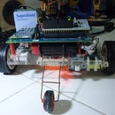
Step 11: Connecting More Things Together and Testing.


Plug the pro mini onto the perf board and plug the male header pins from the tennis ball into the corresponding female header pins on the perf board.
Get the tactile switch and solder it's two pins to 2 wires. After that
solder the two wires to pin 2 of the Pro Mini on the perf board and to GND.
Fit the battery in between the female headers at the bottom of the perf board. It is recommended to zip tie the whole assembly together to prevent it from disconnecting(after intense shaking?) when its used.
Step 12: Putting Everything Together


Get one side of the ball and mark the place where the connectors and button will protrude out of the ball and cut it out. Glue the tactile switch to the spot designated for it and plug the header for that half of the ball into the perf board. This will be the top side of the ball.
Insulate the header pins with electrical tape (to prevent it from touching the resistor pins on the ball) and put the electronics assembly into the top side of the ball. Take the other side of the ball and plug it's headers onto the perf board and then insulate them with electrical tape. Put the bottom side of the ball on and it should close up back into a tennis ball with a big seam in the middle.
The ball is complete. To hold it together I used rubber bands to make the battery removable but you can glue it together if you want.
Step 13: Programming


The coding is done with the Arduino IDE and is programmed into the Pro Mini with a FTDI cable. The code I provided needs the Input Debounce library that can be installed with the Libraries Manager included in the latest version of the IDE.
The code works by using the CrossFade code from Arduino and uses a random() function to change its colour.
The tactile switch is used to put the Pro Mini to sleep and to wake the Pro Mini up using external interrupt.
Change the pin declarations to fit your ball and upload the code. The ball should start crossfading once the code is uploaded.
Attachments

Step 14: Finished.


The RGB LED Tennis ball is complete. Tpo power off the ball press and hold the button until the green light comes on, then let go. The ball should slowly fades off. The ball is now off (the MCU is sleeping). To power it on, press the button briefly. it should power on now.
I charged the whole thing to full then kept it on till the battery low LED comes on and it took about 4 hours until the battery low LED comes on.
Thank you for reading this instructable. If you have made your own RGB LED Tennis Ball, do click the 'I made it' and post a picture of it running. If you have any questions or suggestions do post it in the comments section.
Thank you once again for reading this instructable and God bless...

Participated in the
Tech Contest

Participated in the
Spectacular Failures Contest

Participated in the
Make It Glow! Contest


