

Introduction: ROOM MAPPING Arduino Robot With Unity 3D


This project uses an Arduino robot running a ESP-8266 Node MCU that communicates (and drives around) with a mobile phone. The phone is running an app made in the video game engine Unity 3D that does 3 things:
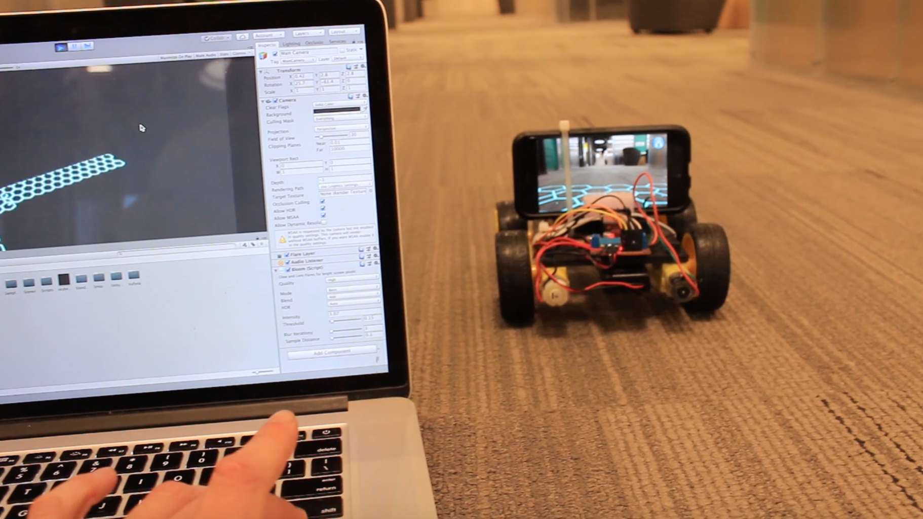
1.) The first scene allows you to drive around the robot with a camera feed going back to your computer. You can use the arrow keys to drive it around in any direction and the video feed allows you to keep driving even when the robot is out of sight.
2.) The second scene allows the robot to track anything you put in front of it. You can click the screen to initialize the tracker and then the robot will follow around that object.
3.) The third scene allows you to drive the robot with your computer using the arrow keys. The app uses an augmented reality SDK to find the walls and ceiling which it sends back to your laptop giving you a digital representation of your environment.
Parts:
ESP-8266 Node MCU https://amzn.to/2NIvCbu
l298N Motor Driver: https://amzn.to/2NKlRK4
Assorted Arduino Wires: https://amzn.to/2tyjPTS
Robot Chassis, wheels, battery: https://amzn.to/2udtBMb
Unity App:
Step 1: Assemble Your Robot

So I built my robot with spare 3D printed parts I had but you could use a DVD case or a any other small flat piece of plastic. I linked to a chassis on Amazon in the intro which you can use but the Arduino code would be slightly different. I had all my motors facing the same direction but they face opposite directions in the prebuilt chassis so just be aware of that.
Either way, use hot glue or some other adhesive to attach your motors and Arduino parts to the chassis.
Glue your battery box to the underside of the robot. The wheels will just snap on to the geared DC motors.
I have a second battery underneath my robot. I hot glued a usb power bank to the underside in addition to the 9V battery in order to power my Node MCU separately for prolonged battery life during development but you could just get away with the 9V battery if you want.
In order to hold the phone in place I used an "L" shaped piece of plastic and a zip-tie. I am sure there are other (better) ways to do this.
Step 2: Make the Connections!

To connect the motors and Arduino board we will use an l298N dual H bridge, this among other things allows us to spin the motors in different directions so our robot can turn in any direction.
This thing can take in up to 12 volts and has an onboard voltage regulator which outputs 5V, the perfect amount for powering our Arduino.
Connect everything according to the diagram above.
Make sure the motors are facing the same direction.
Essentially, the motors on each side are getting wired together so they can being controlled as one motor. This is because the motor controller only allows for a maximum of 3 motors. Even so with two motors we can still get this thing to turn in any direction by making both sides go in opposite directions.
Once you are all set to go, edit the code in the next step to use your network name and password. We do this so your Node MCU can connect to your WIFI network and send packets of information to your phone and computer.
Step 3: Upload This Code!

#include <SoftwareSerial.h>
#include <ESP8266WiFi.h>
#include <WiFiUdp.h>

int incomingByte = 0;

int speed = 1023;//0 to 1023

int enA = 16;//d0
int in1 = 5;//d1
int in2 = 4;//d2

int enB = 14;//d5
int in3 = 0;//d3
int in4 = 2;//d4

//wifi stuff
const char* ssid     = "***********************"; // wifi network name
const char* password = "*****************"; // wifi network password

WiFiUDP Udp;
unsigned int localUdpPort = 1998;
char incomingPacket[255];

void setup(){
Serial.begin(115200);
delay(10);
Serial.println("Motor test!");

// We start by connecting to a WiFi network
Serial.print("Connecting to ");
Serial.println(ssid);
WiFi.begin(ssid, password);
while (WiFi.status() != WL_CONNECTED) {
    delay(500);
    Serial.print(".");
}
Serial.println("WiFi connected");
Serial.println("IP address: ");
Serial.println(WiFi.localIP());
Serial.println("Starting UDP");
Udp.begin(localUdpPort);

pinMode(enA, OUTPUT);
pinMode(enB, OUTPUT);
pinMode(in1, OUTPUT);
pinMode(in2, OUTPUT);
pinMode(in3, OUTPUT);
pinMode(in4, OUTPUT);
}
void right()
{
  digitalWrite(in1, LOW);
  digitalWrite(in2, HIGH);

  analogWrite(enA, speed);

  digitalWrite(in3, LOW);
  digitalWrite(in4, HIGH);

  analogWrite(enB, speed);
}

void left()
{

  digitalWrite(in1, HIGH);
  digitalWrite(in2, LOW);

  analogWrite(enA, speed);

  digitalWrite(in3, HIGH);
  digitalWrite(in4, LOW);

  analogWrite(enB, speed);
}

void forward()
{
  digitalWrite(in1, LOW);
  digitalWrite(in2, HIGH);

  analogWrite(enA, speed);

  digitalWrite(in3, HIGH);
  digitalWrite(in4, LOW);

  analogWrite(enB, speed);
}

void backward()
{

  digitalWrite(in1, HIGH);
  digitalWrite(in2, LOW);

  analogWrite(enA, speed);

  digitalWrite(in3, LOW);
  digitalWrite(in4, HIGH);

  analogWrite(enB, speed);
}

void stop()
{
  digitalWrite(in1, LOW);
  digitalWrite(in2, LOW);
  digitalWrite(in3, LOW);
  digitalWrite(in4, LOW);
}

void ListenPacketRoutine(){
  //listen for packets
  int packetSize = Udp.parsePacket();
  if (packetSize){
    int len = Udp.read(incomingPacket, 255);
    Serial.printf("UDP packet contents: %s\n", incomingPacket);
    if (incomingPacket[0] == 'f'){
        forward();
    } else if (incomingPacket[0] == 'b'){
        backward();
    } else if (incomingPacket[0] == 'l'){
        left();
    } else if (incomingPacket[0] == 'r'){
        right();
    } else if (incomingPacket[0] == 's'){
        stop();
    }
  }
}

void ListenKeyboardRoutine(){

 if (Serial.available() > 0) {
    incomingByte = Serial.read();
    }

 switch(incomingByte)
  {
     case 's':
      { stop();
       Serial.println("Stop\n");
       incomingByte='*';}

     break;

     case 'f':
     {  forward();

       Serial.println("Forward\n");
       incomingByte='*';}
     break;

      case 'b':
    {   backward();

       Serial.println("Backward\n");
       incomingByte='*';}
     break;

     case 'r':
     {
       right();
       Serial.println("Rotate Right\n");
       incomingByte='*';}
     break;

       case 'l':
      {
       left();
       Serial.println("Rotate Left\n");
       incomingByte='*';}
     break;
  }
}

void loop()
{
    ListenPacketRoutine();
    ListenKeyboardRoutine();
}
Step 4: Connect All Devices to Your Network.

All of the communication here is done via WIFI so make sure your phone and computer are all connected to the same local WIFI network.
With your robot plugin in via USB open up the serial monitor in the Arduino IDE to 115200 BAUD.
Hit reset on the Node MCU and wait for the board to connect to your network. It will print out its IP address.
Copy that to your clipboard because we need to get that into our Unity app.
Go to my Github and download and open up this Unity project:
Step 5: The Camera Scene.

First open up the camera scene. If you look on the ARCamera the server script is what takes the video feed from Vuforia and streams it to the computer via TCP.
The controller scene is what receives the video stream and also allows you to use the arrow keys to control the robot. Before you can use this make sure your phone and computer are connected to the same WIFI network. Go to the videoClient game object and put in your phones IP address there. Now go to the keyboard input game object and put in your Node MCU’s IP address in the send message script.
Now this scene is a little bit finicky so in order for it to work you need to first start the camera scene on your phone (we will get to this later) and then once that is already running press play on the controller scene in the editor and you should be able to drive around. The quality is super low for performance purposes but you could bump it up in the server script of the camera scene if you wanted to.
Step 6: The Follow Scene.

The next scene is the follow scene. This scene uses Vuforia’s user defined targets so you can create a trackable object at runtime as long as it has enough feature points. On the robot follow manager make sure to put in the IP address of your Node MCU in the send message script.
When you open up this scene on your phone, put some kind of image in front of the camera and click the screen to initialize a new tracker. If the image has enough feature points it will say image quality high and tracking will begin. I noticed as the battery power diminishes this tracking behavior slightly changes but it will at least work for a while with a new battery. If we open up robot follow behavior you will see that this script just checks if the current image target is within a certain set of bounds and if it isn’t it sends a message to the robot to move for one frame before stopping. This doesn’t result in the smoothest behavior but it works pretty decent.
Step 7: The Mapping Scene

Now this last scene uses Apple's ARkit because I wanted it to detect vertical and horizontal planes (which Vuforia does not do yet) so it will only work on IOS.
If we open up the mapping scene make sure to put your computers IP address on the SendMessageBehavior.cs script. This script sends the name, position, rotation, and scale of the generated planes back to your computer as ARkit instantiates them. This gets received from the MapController scene where all the planes will be displayed on your computer. In here make sure to put the IP address of your Node MCU in the send message script, so you can drive it around with the arrow keys.
Step 8: Let's Put the App on Your Phone!

First go to file -> build settings -> player settings -> and put in something for your bundle identifier. Also, make sure there is something in the box for camera usage description.
If you are building for Android go to build settings and switch your platform to Android, uncheck Android TV in your player settings. Hit build and run with your phone plugged in.
If you are building out to an iPhone or and iPad, make sure to download Xcode from the app store. Also, sign up for a free apple developer account from www.apple.developer.com. Go to file and hit build. Open up the file that was created from Xcode and plug in your phone. Choose your development team and hit the play button.
Have fun and let me know if you have any questions in the comments!


