

Introduction: Raspberry PI Light Controller
This instructable will cover how to create your own light show sync'd to music for Halloween or Christmas. You should have a FIRM understanding of electricity and electrical components.
****WARNING****WARNING****WARNING****WARNING***
There is a great risk of shock, fire, personal injury or even death if you attempt this. PLEASE MAKE SURE YOU UNDERSTAND ELECTRICITY AND ELECTRICAL COMPONENTS.
I will not be held responsible or liable for anything that happens should you attempt this instructable.
Step 1: Materials

Materials for this Instructable are easy to obtain both online and in local retailers. I will provide you links to what I used but please shot aroundf or better prices.
1. 1x - Raspberry PI B+ (any PI will work but I used a B+) w/ 4gb SD card - https://www.amazon.com/SainSmart-101-70-102-8-Chan... - $34
2. 1x - FM Transmitter - https://www.amazon.com/Signstek-Broadcast-Transmit... - $50
3. 2x - 8 Channel Sainsmart Relay Boards - https://www.amazon.com/SainSmart-101-70-102-8-Chan... - $11 each
4. 1x - Edimax Wifi Dongle - https://www.amazon.com/Edimax-EW-7811Un-150Mbps-Ra... - $9
5. 1x - Jumper Wires - https://www.amazon.com/Phantom-YoYo-Dupont-Cable-F... - $6
6. 1x - Electrical Wire - http://www.homedepot.com/p/Cerrowire-25-ft-14-2-UF... - $13
7. 1x - In-Sure Connectors - http://www.homedepot.com/p/Ideal-34-Yellow-In-Sure... - $8
8. 1x - Sacrificial Extension cord or buy a plug - http://www.homedepot.com/p/Leviton-15-Amp-125-Volt... - $4
9. 8x - Household Plugs - http://www.homedepot.com/p/Leviton-15-Amp-Groundin... - $1 each
10. 2x - Electrical Outlet Housings - http://www.homedepot.com/p/4-Gang-Hard-Shell-Wall-... - $5 each
11. 2x - Face Plates - http://www.homedepot.com/p/Leviton-Decora-4-Gang-M... - $4 each
12. Electrical Tape
13. Screw Drivers
14. Scrap wood or housings for mounting -
15. A computer and knowledge/time to set up the light show
16. KNOWLEDGE OF ELECTRICITY
Step 2: Building the 125v Circuitry

The first step is to build your circuitry in preparation of the show. DO NOT OVER STRIP YOUR WIRES, YOU DO NOT WANT EXPOSED WIRE THAT COULD DELIVER A SHOCK!
- I connected both 8 channel relay boards to my scrap piece of plywood. I flipped the second board upside down so that the pins used to connect the Raspberry PI on both boards faced the gap between the 2 boards and were about 6 inches apart.
- Wire the positive (power) bus around the relays. Make sure you are using wire that is capable of handling the 125v load coming from the house like what I listed in the supplies step. There are 3 screws for each relay module. The bus for the incoming power will go into the center screw on each relay. Use the In-Sure connectors (or wire nuts) to bridge the incoming power into the center screw of each relay on both boards.
- Mount both of your plug housings to your board. I just used screws through the inside of the housing into the plywood.
- On all 8 electrical outlets there will be 5 screws. 1 green which is for the ground. 2 Silver which are for your neutral and 2 gold which are for your positive (power). By default you will only need to use the ground screw, 1 neutral and 1 positive. Between the gold screws there will be a metal bridge sticking up that connects the top screw to the bottom screw meaning if you power 1 screw, both outlets become active. We don't want this. Break the bridge cleanly off to ensure the top and bottom screws are now completely separated.
- Pay Attention to how you wire this step and ensure you know which outlet corresponds to each relay. I marked mine with masking tape and a pen over the outlet face. Run a wire (capable of handling 125v) from each of the common out screws on the relay (it's the screw where the top line doesn't connect to anything) through your electrical outlet housing and into one of the gold screws on your outlets. After running each of the 16 common outs to their corresponding gold screw go to the next step.
- Create a neutral bus. Using the In-Sure connectors (or wire nuts) run a wire (capable of 125v) through each electrical outlet housing and to 1 of the silver screws on your outlet. The wire from each silver screw will be bridged together into 1 long wire. Since we did not take the metal bridge off of the silver screws we only need to run a wire to 1 silver screw on each outlet instead of both.
- Just like with the neutral bus we will use 125v capable wire to run a wire to each of the ground screws. Run your wire through your housing and to the green (ground) screw on the outlet. Just like before these will all be bridged together into 1 long chain.
- Mount your outlets securely to the housing using the provided screws and then cover them with the faceplates.
- Hooking the circuit to power. I used a plug similar to what I put in the supplies that allows me to run my own wires into the plug and screw them in place. I used the In-Sure connectors to wire mine so I ran a wire off an open port from each bridge into the corresponding screw of my plug. You will need 1 wire off the power bridge from step 2, 1 from the neutral bridge in step 6 and 1 from the ground bridge in step 7.
Once this is all hooked up you will have completed the wiring for the 125v section of this tutorial. See how to wire the relays to receive power and data from the Raspberry PI next!
Step 3: Building the Raspberry PI Circuit
Now we will build a second electrical circuit to actually flip the relays on and off using the Raspberry PI.
- I powered my relays using both the 5v pin on the Pi as well as an external power source. For my external power sources I found old USB based phone chargers. Each individual relay requires up to 30 milliamps to flip. This means each board needs 240 milliamps to flip all relays at once. The relays I bought (please check your board's specs as they can change with each board revision) support up to 2 amps. The power supply you choose needs to have 5v output with less than 2 amps output. The chargers I found were 5v and 800 milliamp output.
- Cut the connector off your charger where it would plug into the phone. If you used USB charging like I did you will see 4 wires when you strip the outside protective casing back a bit. The wires TYPICALLY are as follows:
A. Red - Positive (power)
B. Black - Ground
C. White - USB Data +
D. Green - USB Data - - Cut 1 end off of 2 jumper wires. Strip the cut off end to expose the bare wire (about an inch long). I used a red and a black wire to match what is inside of the USB cable.
- Strip the Red and Black wires of the USB exposing the bare wire (about an inch long)
- Twist the wire from the red jumper wire to the red wire of the usb and cover the joint in electrical tape.
Twist the wire from the black jumper wire to the black wire of the usb and cover the joint in electrical tape.
Repeat steps 2 - 6 for the second charger.
On the relay there will be 3 pins with a blue jumper on them. The 2 end pins are Ground (GND) and JD-VCC. Remove this jumper. Do this for both Relay boards.
For each relay board plug the red jumper wire from 1 of your chargers onto the JD-VCC pin and the black wire to the Ground pin.
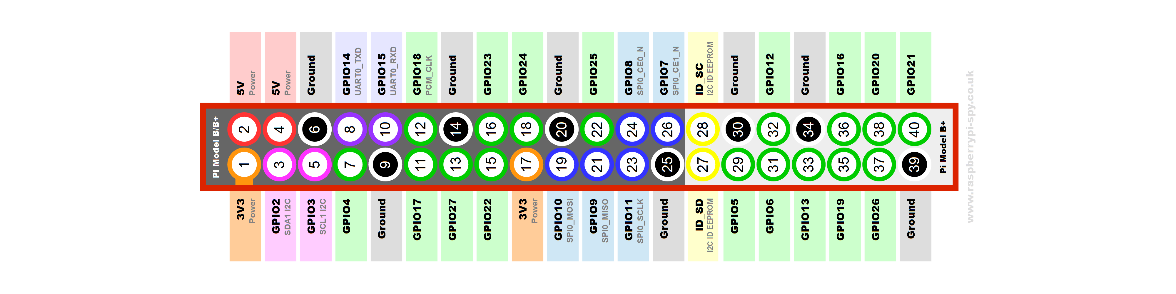
Next we will begin connecting the Raspberry Pi to the relays. There are 2 5v GPIO pins on your Pi. Run a cable to each relay from a 5v pin. It will plug into the 5v (may say vcc) pin on the relay. NOTE: This is a seperate pin than talked about in steps 8 and 9. Here is a GPIO layout for the B+ http://www.raspberrypi-spy.co.uk/wp-content/upload...
Now run 16 jumpers from your other GPIO outputs to the 16 pins of the relays (8 each board). Note: At the end of the pins there is a ground pin that we will NOT put a wire to. This prevents a completed circuit and makes the Raspberry PI isolated from the additional current provided by the external power supply.
Connect the audio cable from your FM transmitter into the audio out jack on the Pi.
Step 4: Setting Up the Pi With Falcon Christmas Player (FPP)
- Download and install the latest version of Falcon Player. Instructions on the download and installation are provided in this thread and won't be covered.
Step 5: Create Your Light Show!
- I used a software called Vixen to create my light show. You can download and install the software here: http://www.vixenlights.com/
- Once it is installed you will need to click "Setup Display"
- On the right side under controllers select "Generic Serial" from the dropdown list and click the green + button.
- Give your Raspberry Pi a name and click OK.
- Outputs on this controller - Set this to 16 as we are using 16 channels and click ok
- On the left hand side select which type of item you are adding to your show. I typically chose Single Element. Add 16 channels to control on the left pane.
- Now we need to assign our elements each to a channel. Highlight 1 element on the left and 1 channel on the right then click the "Patch Elements" button. Continue this process until each unique element is patched to a unique output on your controller.
- Click the "OK" button at the bottom when you are done.
- Click the "Setup Previews" button. Then click "Add New Preview" and select "Vixen Display Preview" and click ok.
- In the Previews Configuration Window you will now see your new preview listed. Select it and click "Configure Preview"
- Here you can add a picture of your house and draw the lights onto the picture. When you do this you can assign one of your elements to each thing you draw. This allows you to preview what it will look like while creating your show.
- On the main Vixen window click "New Sequence"
- Click the Music icon from the tool bar and select the mp3 you wish to use for your show and this will add it into the window.
- From here you can drag the effects (if you have equipment to support it) into each of your elements which are listed down the side. You can resize them to extend or shorten the effect. Do this for the entire song to make your lights dance. (Save often, it crashes for me sometimes).
- When your show is done click Sequence then Export.
- Change the output format to "Falcon Player Sequence" and click the Start button. Save it to wherever you will find it later.
Step 6: Set Up Your Light Show!

- If you have not already done so, plug in your wireless adapter and configure your Pi to use the wireless.
- Access your Falcon Player URL from a web browser. Click on Content then File Manager.
- Upload each of your .fseq files you exported from Vixen as well as the audio files that go with them.
- Click on Content then Playlists. Create a new play list and using the dropdowns, marry the audio and fseq file that go together and click add. Make sure to click SAVE when done or your changes will not be accepted.
- Click on Content then Scheduler. Here you can create a schedule on when your show will automatically turn off and on.
I hope you have enjoyed this Instructable and if you do attempt it please remember that the electrical components are very dangerous and you should not attempt them if you do not have a good understanding of electricity.

Participated in the
Amps and Speakers Contest 2016


