

Introduction: Raspberry Pi GPIO Circuits: Controlling High Powered Components With a Transistor


In our earlier Instructable, we showed you how you can use your Raspberry Pi's GPIO pins to switch an LED on and off.
The Raspberry Pi's GPIO pins are only capable of supplying a low amount of power. If you try to power a component that requires a lot of power, you can cause permanent damage to the Raspberry Pi.
In this Instructable, we aim to show you how to get around this issue by using a Transistor. Transistors can be used as a switch in a circuit, enabling you to control a higher power component without damaging your Raspberry Pi's GPIO pins.
Step 1: What You Will Need


- A RaspberryPi with Raspbian already installed. You will also need to be able to access the Pi using a Monitor, Mouse and Keyboard or via Remote Desktop. You can use any model of Raspberry Pi. If you have one of the Pi Zero models, you may want to solder some header pins to the GPIO port.
- A Solderless Prototyping Breadboard
- 1 x 330 ohm Resistor
- 1 x 1 K ohm Resistor
- Some Male to Female jumper wires
Step 2: Build Your Circuit
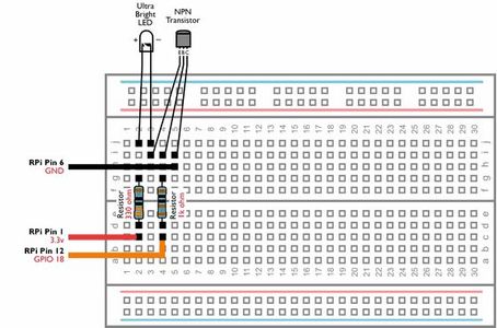
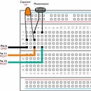
Build the above circuit on your breadboard making sure that none of the components leads are touching, the LED is connected the correct way round and the Transistor is connected correctly.
If you look at the LED closely, you will see that it has two small pieces of metal inside the coloured casing. These are called the Anode and Cathode. The Cathode is the largest of the two and is also connected to the LED's negative lead. Ensure that the switches are connected the correct way round.
To identify which leg is which on the transistor, hold the flat surface towards you. The Emitter (E) is the pin on the left, the Base (B) is in the centre and the Collector (C) is on the right.
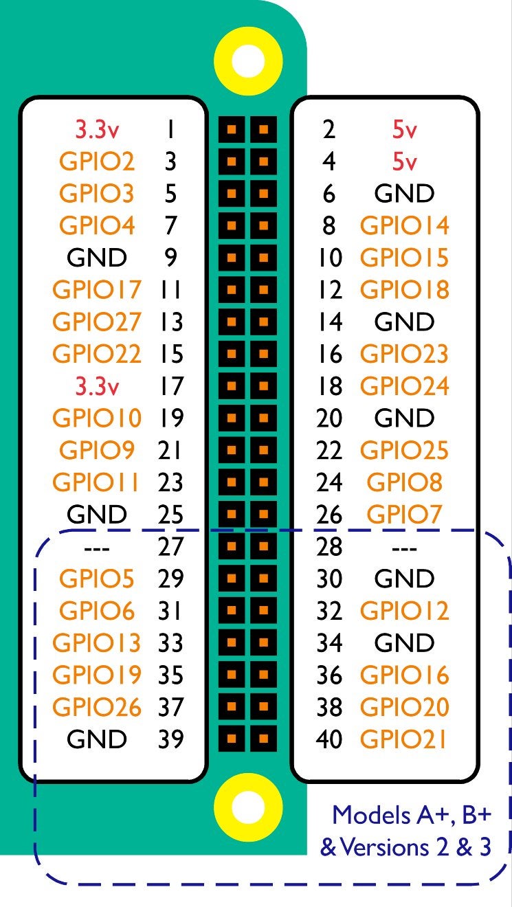
Once you have checked your circuit, connect the jumper cables to your Raspberry Pi's GPIO pins by following the above diagram.
Step 3: Control the LED by Running Python Commands

We will now write a short script that will power the LED on and off via the Transistor.
On your Raspberry Pi, open IDLE (Menu > Programming > Python 2 (IDLE)).
Open a new project go to File > New File. Then type (or copy and paste) the following code:
import RPi.GPIO as GPIO
import time
GPIO.setmode(GPIO.BCM)
GPIO.setup(18, GPIO.OUT)
while True:
    GPIO.output(18, True)
    time.sleep(1)
    GPIO.output(18, False)
    time.sleep(1)
Save your project as bright.py (File > Save As) in your Documents folder.
Now open Terminal (Menu > Accessories > Terminal) and type the following command:
python bright.py
The ultra bright LED will now blink. You can stop this program from running by pressing CTRL+Z.
In this circuit, the transistor acts like a switch. The GPIO.output command instructs the Raspberry Pi to emit a small current from GPIO pin 18.
When this small current is applied to the Base pin (which is currently connected to GPIO pin 18), the transistor allows a larger current to flow between the collector and emitter (which are connected to Ground and the LED respectively).
Therefore, the ultra bright LED is drawing its power directly from the Raspberry Pi's more capable Ground and 3.3v Pins, but can still be controlled by a much smaller current from the GPIO pins.
