

Introduction: Raspberry Pi GPIO Circuits: Using an LDR Analogue Sensor Without an ADC (Analogue to Digital Converter)


In our earlier Instructables, we have shown you how you can link your Raspberry Pi's GPIO pins to LEDs and switches and how the GPIO pins can be High or Low. But what if you want to use your Raspberry Pi with an analogue sensor?
If we want to use analogue sensors with the Raspberry Pi, we would need to be able to measure the resistance of the sensor. Unlike the Arduino, the Raspberry Pi's GPIO pins are unable to measure resistance and can only sense if the voltage supplied to them is above a certain voltage (approximately 2 volts). To overcome this issue, you could use an Analogue to Digital Converter (ADC), or you could use a relatively cheap capacitor instead.
This Instructable will show you how this can be done.
Step 1: What You Will Need


- A RaspberryPi with Raspbian already installed. You will also need to be able to access the Pi using a Monitor, Mouse and Keyboard or via Remote Desktop. You can use any model of Raspberry Pi. If you have one of the Pi Zero models, you may want to solder some header pins to the GPIO port.
- A Light Dependant Resistor (Also known as an LDR or Photoresistor)
- A Solderless Prototyping Breadboard
- Some Male to Female jumper wires
Step 2: Build Your Circuit
Build the above circuit on your breadboard making sure that none of the components leads are touching. The Light Dependent Resistor and Ceramic Capacitor have no polarity which means that a negative and positive current can be connected to either lead. Therefore you do not need to worry about which way these components have been connected in your circuit.
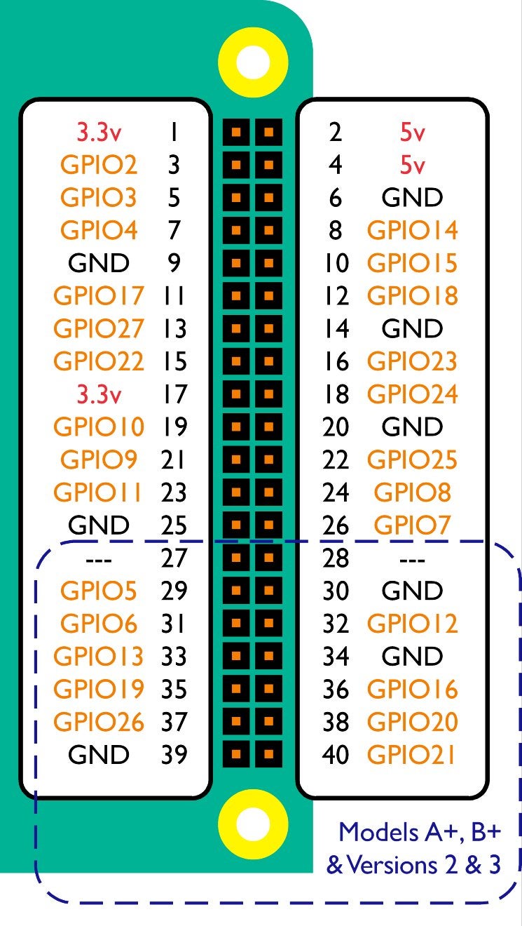
Once you have checked your circuit, connect the jumper cables to your Raspberry Pi's GPIO pins by following the above diagram.
Step 3: Create a Python Script to Read the Light Dependant Resistor

We will now write a short script that will read and display the resistance of the LDR using Python.
On your Raspberry Pi, open IDLE (Menu > Programming > Python 2 (IDLE)). Open a new project go to File > New File. Then type (or copy and paste) the following code:
import RPi.GPIO as GPIO<br>import time<br>mpin=17
tpin=27
GPIO.setmode(GPIO.BCM)
cap=0.000001
adj=2.130620985<br>i=0
t=0
while True:
    GPIO.setup(mpin, GPIO.OUT)
    GPIO.setup(tpin, GPIO.OUT)
    GPIO.output(mpin, False)
    GPIO.output(tpin, False)
    time.sleep(0.2)
    GPIO.setup(mpin, GPIO.IN)
    time.sleep(0.2)
    GPIO.output(tpin, True)
    starttime=time.time()
    endtime=time.time()
    while (GPIO.input(mpin) == GPIO.LOW):
        endtime=time.time()
    measureresistance=endtime-starttime

    res=(measureresistance/cap)*adj
    i=i+1
    t=t+res
    if i==10:
            t=t/i
            print(t)
            i=0
            t=0
Save your project as lightsensor.py (File > Save As) in your Documents folder.
Now open Terminal (Menu > Accessories > Terminal) and type the following command:
python lightsensor.py
The Raspberry Pi will repeatedly display the resistance of the photoresistor. If you place your finger over the photoresistor, the resistance will increase. If you shine a bright light on the photoresistor, the resistance will decrease. You can stop this program from running by pressing CTRL+Z.
Step 4: How It Works
As the capacitor gradually charges, the voltage that passes through the circuit and to the GPIO pin rises. Once the capacitor is charged to a certain point, it's voltage rises above 2 volts and the Raspberry Pi will sense that GPIO pin 13 is HIGH.
If the resistance of the sensor increases, the capacitor will charge more slowly and the circuit will take more time to reach 2 volts.
The above script essentially times how long it takes for pin 13 to turn High and then uses this measurement to calculate the resistance of the Photoresistor.


