

Introduction: Ryerson MEC830 Mechbot Custom Serial Communication


Future students for Ryerson’s MEC830 course may find this snippet of code useful. I wrote it in order to assist my group in accomplishing our culminating project. The main purpose of the code is to utilize the only available pins on both the Mechbots and EVShield to allow for serial communication.
Communication between the Mechbot and EVShield was important because required tasks could only be completed successfully if both Arduino’s could communicate back and forth. For example, if a coloured ball was being picked up, the Mechbot IR sensors would need to identify if the ball was on the left, right, or directly in front of the cart. The resulting information was then relayed to the EVShield in order to move the lego NXT arm to the correct location.
The example above demonstrates the communication problem; namely, when you are restrained to sending a high or low signal, how do you send a signal to differentiate between a multitude of outcomes?
This tutorial will explain how I’ve implemented my own algorithm for serial communication between two Arduino’s and two sets of pins.
Step 1: Building Your Own Mechbot and EVShield (Sorta)
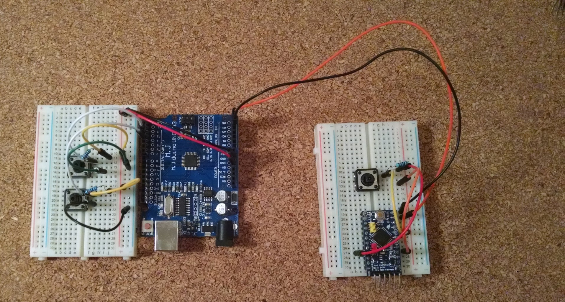

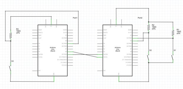
Since both Mechbot and EVShield are controlled by an Arduino, you can rig up two Arduinos to test this code. Due to limited time in the labs, I found it much easier to debug this section of the code by replicating my own version at home.
Communication pins:
Mechbot: Pins PC4 and PC5
EVShield: Pins PB1 and PB0
Push Buttons pins:
Mechbot: PD3, PD4
EVShield: PD5
Step 2: Sample Sequence


In order to explain the solution, the photo above will be referenced in the explanation. The following is a sequence of events that must occur in order to pick up the ball.
- The Mechbot car must self navigate up to the T-Junction and stop.
- The Mechbot car must determine whether the ball is on the left side or right side of the cart.
- The Mechbot car then sends the location value to the EVShield.
- The EVShield interprets the code sent from the Mechbot.
- The EVShield picks up the ball
- When all the actions to pick up the ball are completed, a competion signal is sent from the EVShield to the Mechbot.
- The Mechbot continues happily along the path.
Steps 3 and 6 require communication and to begin the process of transmitting data, a code appendix is defined by the user, (photo 2). The most significant bit in the code indicates to the receiver that a transmission is being sent (1). The next 3 bits are representative of the actual code, and the least significant bit indicates to the receiver that the whole message has been sent (0).
By creating a code that is universal to both Arduinos, instructions can easily be communicated between the two devices. When an instruction is sent by the Mechbot, the Mechbot will remain in a period of hiatus where it waits for a completion signal from the EVShield. Only when a completion signal is received does the Mechbot continue with its functions.
Step 3: Algorithm for Receiving and Transmitting Data
In order to transmit data, I've written two functions to carry out this process, they are: send_data(int num) and completion_Scan().
I have assigned variables with the code corresponding to my table for the first 2 scenarios called right and left. For this example we will only focus on communicating that the ball is on the left or right side. When the location of the ball is determined, the value is sent to the send_data function where the integer is broken up into an array and the values pulsed high(1) or low(0). When all the values are pulsed, the completion_Scan() function is called and only exits when a completion signal is sent from the original Arduino that received the message.
pseudo code:
int right=10100;
int left = 10010;

if (ball is on left side){
	send_data(right);
	completion_Scan();
}
if (ball is on the right side){
	send_data(left);
	completion_Scan();
}
When send_Data is called, the integer passed is chopped into a 5 bit array by using the following algorithm:
int send_data(int num){
    data[4] =  num % 10;
    data[3] = (num % 100 - data[4])/10;
    data[2] = (num % 1000 - data[3] - data[4])/100;
    data[1] = (num % 10000 - data[2] - data[3] - data[4])/1000;
    data[0] = (num % 100000 - data[1] - data[2] - data[3] - data[4])/10000;
By using the modulo function, I've created an algorithm for storing the individual bits into a unique array position called data. For example, if 10100 is sent to send_data, then data[4] will store the remainder of 10100 divided by 10.
data[4] = (10100 mod 10) = 0;
data[3] = ((10100 mod 100) - 0 ) / 10 = 0
data[2]= 1
data[1]=0
data[0]=1
The entire data array is processed through a "for" statement and whenever a value of 1 is detected, a high signal is pulsed through the wire for 200ms. Conversely, whenever a value of 0 is detected, a low signal is pulsed through the wire for the same amount of time.
for (y=0; y<5; y++){
	//send high or low
	if (data[y]==1){
		turn PC5 HIGH
	}
	else{
		turn PC5 LOW
	}
	delay(200);
}
In order to receive data, the receiving Arduino is always waiting for an initial high signal. Immediately after it is detected, the message being sent is stored into an array in a similar fashion. The final code received is then compared to determine the desired output.
I've included the full code for both Mechbot and EVShield. The only difference is I have included Serial.prints for debugging, push buttons to send or terminate communication, and blinking an LED during transmission. Note: you can download both files or right click and select "open in new tab" to view the code.

Step 4: Good Luck


I hope my code helps you with your project, best of luck!


