

Introduction: Seeed LoRa IoTea Solution


An automatic information collection system applied to tea plantation. It is part of intelligent agricultural information collection.
Step 1: Things Used in This Project
Hardware components
- Grove - Carbon Dioxide Sensor(MH-Z16)
- Grove - Digital Light Sensor
- Grove - Dust Sensor(PPD42NS)
- Grove - Oxygen Sensor(ME2-O2-Ф20)
- Soil Moisture & Temperature Sensor
- LoRa LoRaWAN Gateway - 868MHz Kit with Raspberry Pi 3
- Grove - Temp&Humi&Barometer Sensor (BME280)
Software apps and online services
- Microsoft Visual Studio 2015
Step 2: Story
Smart agriculture is to apply the Internet of Things technology to traditional agriculture, using sensors and software to control agriculture production through mobile or computer platforms, making traditional agriculture more “smart”.
On Mengding Mountain northeast of Ya’an, Sichuan, the mountain ridge runs west to east in a sea of green. This is a most familiar sight for 36-year-old Deng, one of the very few Mengding tea makers of his generation, with a plantation of 50mu (=3.3 hectares) situated at 1100m abovesea level. Deng comes from a family of tea makers, but carrying on the family legacy is not an easy task. “Our teas are grown at high altitude in an organic environment to ensure its excellent quality. But at the same time, the growth density is low, cost is high and budding is uneven, making tea hard to harvest. That’s why high-mountain teas are normally small harvests and their values are not reflected on the market.” For the past two years, Deng has been trying to raise consumer awareness of high-mountain tea to promote their value. And when he met Fan, who was looking for a plantation to implement Seeed’s IoTea technology, a perfect match for a solution was made. The Seeed IoTea Solution aims to assist tea farmers better manage plantations without altering the traditional practices of tea cultivation, and to present real-time environmental data from the plantationson an open platform.
Consisting of sensors, nodes, and gateways, IoTea collectsreal-time data of factors that may affect the quality of tea during cultivationand production processes, including temperature and humidity, CO2, O2, PM, and light exposure. The data is collected by the sensors, sent by the nodes to the gateway and eventually to the cloud, and is made accessible to end customers on a webpage.
Step 3: Hardware Connection
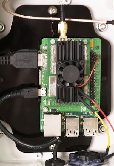
Step1: Gateway Connection
The gateway is installed separately in a box. Considering the heat dissipation problem, we added 2 fans. One is for Raspberry Pi’s heat dissipation, the other is for internal and external air circulation. The gateway box is placed in a farmer’s home, so we don’t need to consider its power problem.
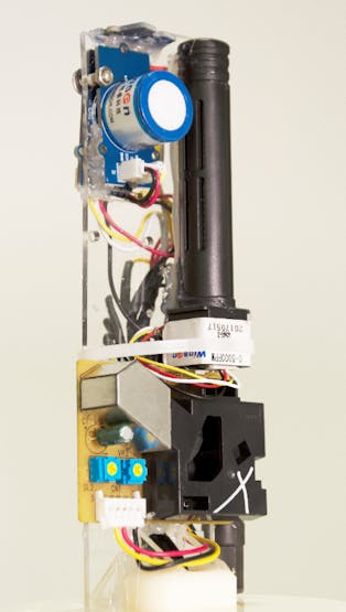
Step2: Node Connection
The node is terminal of the data, and all the original data is obtained from here. There are 6 sensors connected to the node.In addition to the soil moisture & temperature sensor, we put other sensors inside the louver box.

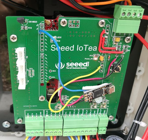
Node is placedin a waterproof box. In order to have a better connection to the node, we make an adapter board. At the last, we will provide this board’s schematic’s download link. As shown below, the cables of sensors are plugged into adapter board through terminal blocks. We use 3 MOS tubes (SI2301) to build switch circuits to control the on and off of sensors and fan. Fan is used to cool down. We have a temperature sensor(DS18B20) mounted on the board. It can tell us the internal temperature of the box, and then microcontroller decides whether to turn on fan. We use several resistors to make a voltage divider circuit to measure lead-acid battery voltage. Finally, we reserve 3 IIC interfaces and serial port on the board for later expansion and debugging.
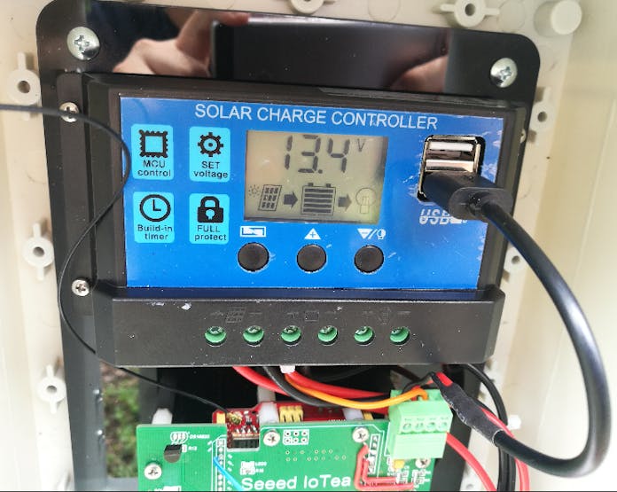
Let’s talk about node’s power supply problem. The node is placed in tea plantation randomly, so traditional power supply method is no longer applicable. Using a solar power solution is a good idea. There are many solutions provided on the market currently. We can select one of them that meets our needs. There are 3 parts in the solution we chose: solar panel, solar charge controller and lead acid battery. In order to capture the solar energy better, we put solar panel on the top of the bracket and adjust its angle to ensure that it is facing the sun. We placed solar charge controller into the same box with node. Because of there is no extra space inside the box, we had to find a new waterproof box to place the lead acid battery.


Step 4: Software Configuration
Node
In this section, we will introduce the mainly software configuration of node.
DataFormat
Data uploaded by the node to the gateway:
unsigned char Lora_data[15] ={0,1,2,3,,4,5,6,7,8,9,10,11,12,13,14};
Meaning of each data bit:
Lora_data[0]:Air temperature, ℃
Lora_data[1]:Air humidity, %
Lora_data[2]:Altitude high eight, m
Lora_data[3]:Altitude low eight
Lora_data[4]:CO2 concentration high eight, ppm
Lora_data[5]:CO2 concentration low eight
Lora_data[6]:Dust concentration high eight, pcs/0.01cf
Lora_data[7]:Dust concentration low eight
Lora_data[8]:Light intensity high eight, lux
Lora_data[9]:Light intensity low eight
Lora_data[10]:O2 concentration, % (raw data divided by 1000)
Lora_data[11]:Soil temperature, ℃
Lora_data[12]:Soil humidity, %
Lora_data[13]:Battery voltage, v
Lora_data[14]:Sensors error code
Error code:
Lora_data[14] = [bit7, bit6, bit5,bit4, bit3, bit2, bit1, bit0]
Meaning of each bit:
bit 0: 1----Temp & Humi & Barometer Sensor (BME280) error
bit 1: 1---- Carbon Dioxide Sensor(MH-Z16) error
bit 2: 1---- Dust Sensor(PPD42NS)error
bit 3: 1---- Digital Light Sensor error
bit 4: 1---- Oxygen Sensor(ME2-O2-Ф20) error
bit 5: 1---- Soil Moisture & Temperature Sensor error
bit 6: Reserved
bit 7: Reserved
We have made a Error_code_transform.exe, open it and input error code in hexadecimal, you will quickly know which sensor is error. Download link is at the end of this article.
Parameter adjustment:
a)Data transmission cycle
// seeedtea.ino
#defineinterval_time 600 //second
This parameter can be varied to change data transmission cycle. In each cycle, data acquisition takes about 1 minute. So, it is not recommended to change this value to less than 60 seconds.
b)Dust sensor warm-up time
//seeedtea.ino
#definePreheat_time 30000 //DustSensor warm-up time,  milliseond
//Dust_other.cpp
#definesampletime_ms 30000 //samplingtime30s
c)Voltage coefficient
//POWER_Ctrl.cpp
#defineBattery_coefficient 0.159864 //ADC value× Battery_coefficient = battery_voltage
#defineSolar_coefficient 0.22559  //ADC value × Solar_coefficient = solar_voltage
These two parameters are calculated based on the voltage divider circuit.
d)Fan opening temperature threshold
//POWER_Ctrl.cpp
#defineFan_start_temp 45 //temperaturethreshold
#defineFan_start_light 500 //light intensity
When actual temperature exceeds the threshold, fan will start to cool down.
e)O2 sensor initialization parameter
//Oxygen.cpp
#defineO2_percentage 208.00   //20.8%
f) Macro switch
//seeedtea.ino
#defineLORA_RUN //After the comment, Lora initializationand data transmission will stop
#defineSENSOR_RUN //After the comment, externalsensors will stop working
//POWER_Ctrl.cpp
#defineFAN_ON //Fortesting only, Practical application needs to be commented out
/*******DS18B20 control mode **********************/
#defineSlower_Mode // Slow mode toget the temperature. Comment out is fast mode
g)Pin mapping
D2: LED indicator and external reset microcontroller
IIC: SCL and SDA
//Dust_other.h
#defineDust_pin 3 //Dust sensor
//CO2.cpp
#defineCO2_serial Serial1 //use hardwareserial port (D0 & D1)
//seeedtea.ino
#definedataPin 6 //Soil data pin
#defineclockPin 7  //Soil clock pin
//POWER_Ctrl.h
#defineDS18B20_pin 8 //DS18B20
#defineFan_pin 9 //Fan
#defineAir_CtrlPin 10  // Control pin for the sensors placed in louverbox
#defineSoil_CtrlPin 11 // Soil Moisture & Temperature Sensor switch pin
#defineBattery_pin A2  // Measure battery voltage
#defineSolar_pin A3 //Measure solar panelvoltage
//Oxygen.h
#defineO2_pin A1  //O2 sensor
h)Watchdog timer
The watchdog timer is used to monitor system running status. When system is running abnormally, node will be reset, so that it can run continuously for a longtime.
The library to be referenced:
- Adafruit_SleepyDog.h has been added to the project
- Adafruit_ASFcore-master.zip is packaged in theproject folder and needs to be manually added to the Arduino IDE.
Related functions:
- Enable watchdog
int WatchdogSAMD::enable(int maxPeriodMS, bool isForSleep)
Input parameters:
Int maxPeriodMS: Waiting time in milliseconds. The maximum allowed is 16000 milliseconds.
return value:
Int type, return the actual waiting time
- Reset watchdog
void WatchdogSAMD::reset()
Call this function to reset the watchdog timer, referred to as "feeding the dog." Exceeding the wait time without reset will cause node to restart.
- Stop watchdog
void WatchdogSAMD::disable()
Gateway
In this section we will introduce how to connect to Loriot server.
Step1: Loriot Server Gateway Registration
a) New user need register an account first, click registration address. Fill in UserName, Password and email address to register, after registration an email will be sent to you, please follow the instruction in the email to activate.
b) After successful activation, click here to log in. Default tier is “Community Network”, it supports 1 Gateway(RHF2S001) and 10 nodes.
c) Enter Dashboard -> Gateway, click Add Gateway start to add Gateway.
d) Select Raspberry Pi 3
e) Set as below:
- Radio front-end -> RHF2S001 868/915 MHz (SX1257)
- BUS -> SPI
f) Fill in the MAC address of your RHF2S001, should be in format of b8:27:eb:xx:xx:xx. And also input Gateway Location information.
g) Click “Register Raspberry Pi gateway” to finish the registration.

h) Click the registered gateway to enter configuration page, switch “Frequency Plan”manually, your plan here is decided by the type of your RHF2S001 type, available plan is CN470,CN473, CN434,CN780,EU868, after selected please refresh the page to get the exact channel. In this wiki we choose EU868.
i) Run the command in the putty terminal:
cd /home/rxhf/loriot/1.0.2
sudo systemctl stop pktfwd
sudo gwrst
wget <a href="https://cn1.loriot.io/home/gwsw/loriot-risinghf-rhf2s008-rhf1257-SPI-0-latest.bin"> <a href="https://cn1.loriot.io/home/gwsw/loriot-risinghf-r...</a">  https://cn1.loriot.io/home/gwsw/loriot-risinghf-r...>> -O loriot-gw.bin
chmod +x loriot-gw.bin
./loriot-gw.bin -f -s cn1.loriot.io
j) Finish gateway registration. You will see the gateway is Connected now. Next is to register node.

Step2: Loriot Server Connect Node device
a) Get the available gateway channels
Current gateway channels could be got from Dashboard -> Gateway ->Your Gateway, you can see the available channels as the picture below.

b) Seeeduino LoRAWAN GPS(RHF3M076) Configuration
Open the serial monitor of ArduinoIDE, tap the command below.
at+ch
To confirm the default channel of your Seeeduino_LoRAWAN GPS, you will get 3 channels. If there is no available channel, you can change the channels of Seeeduino_LoRAWAN by the command below.
at+ch=0,868.1
at+ch=1,868.3
at+ch=2,868.5
Then you can use at+ch again to check.
c) Add Seeeduino_LoRAWAN GPS as an ABP Node
Log in Loriot server, Click Dash Board->Applications->SimpleApp. Click Import ABP ,input below items
- DevAddr: Seeeduino_LoRAWAN GPS get through"AT+ID" command (Note: Loriot doesn't support colon connector, needremove manually)
- FCntUp:Setto 1
- FCntDn:Setto 1
- NWKSKEY:Defaultvalue 2B7E151628AED2A6ABF7158809CF4F3C
- APPSKEY:Defaultvalue 2B7E151628AED2A6ABF7158809CF4F3C
- EUI:DEVEUI, Seeeduino_LoRAWAN GPS get through "AT+ID" command

Click Import Device button to finish the device import. Now choose Dashboard-> Applications -> SampleApp, you will see the new ABP Node you've just added.

d) Send data from Seeeduino_LoRAWAN
ATTENTION! This is just a test.
Back to serial monitor of ArduinoIDE, send command:
AT+CMSGHEX="0a 0b 0c 0d 0e"
Then go to Dashboard -> Applications ->SampleApp ->Device, click the Node Device EUI or DevAddr, you will find the data you've just sent here.

For details, please refer to this wiki.
Step 5: Website Construction
Related Tools
- virtualenv
- Python3
- Gunicorn
- Supervisor
- Nginx
- MySQL
We use CentOS7 as test deployment environment
virtualenv
Use virtualenv to build a standalone python3 production environment
a) install
pip install virtualenv
b) create a python3 virtual environment
virtualenv -p python3 iotea
c) start the virtual environment and enter iotea directory
source bin/activate
d) exist environment
deactivate
Python3
a) install
yum install epel-release
yum install python36
b) install dependent library PyMySQL,DBUtils,Flask,websocket-client,configparser
pip install pymysql
pip install dbutils
pip install flask
pip install websocket-client
pip install configparser
Gunicorn
a) install (under Python3 environment)
pip install gunicorn
b) run flask project (under iotea project directory)
gunicorn -w 5 -b 0.0.0.0:5000 app:app
c) run websocket-clint to get loriot data
gunicorn loriot:app
d) view Gunicorn process tree
pstree -ap|grep gunicorn
Supervisor
a) install (root user)
pip install supervisor
b) generate config files
echo_supervisord_conf > /etc/supervisord.conf
c) create a directory and introduce a directory configuration
mkdir -p /etc/supervisor/conf.d
Edit /etc/supervisord.conf and modify the files field under [include] at the end of the file.
Note that you need to remove the ';' in front of these two lines, which is the comment character.
[include]
Files = /etc/supervisor/conf.d/*.conf
Means to introduce /etc/supervisor/conf.d/. The following configuration file is used as the process configuration file (monitored by the supervisor).
d) incoming configuration(under iotea directory)
cp iotea.conf /etc/supervisor/conf.d/
cp loriot.conf /etc/supervisor/conf.d/
e) open iotea serve
superviosrctl reload #reload the configuration file
superviosrctl start loriot #open loriot data reception
superviosrctl start iotea #open the iotea flask application
f) other common operations
supervisorctl reload      # reload the configuration file
supervisorctl update
supervisorctl start xxx
supervisorctl stop xxx
supervisorctl status xxx
supervisorctl help        # view more command
Nginx
a) install
yum install -y nginx
b) configuration
cp NginxIotea.conf /etc/nginx/conf.d/
c) start Nginx
systemctl start nginx.service
MySQL
a) related parameters
user='root'
passwd='1234'
db='iotea'
port=3306
b) file
iotea_iotea.sql
c) configuration file
db.ini
Welcome to our website and view data for Mengding tea plantation!


