

Introduction: Self Balancing Robot With Arduino

In this instructable I will show you how to build a self-balancing robot with Arduino, as well as some points to be ware of.
This is how the robot works: MPU6050 module measures the angle, it serves as a feedback to the Arduino microcontroller. The microcontroller gets the difference between the desired angle and the measured angle, does some calculation (PID control algorithm), then outputs to the DC motors. A remote controller controls the movement of the robot. Two nRF24L01+ 2.4GHz modules are used for data transmission between the robot and the remote controller.
Update1 - 27.07.2017:
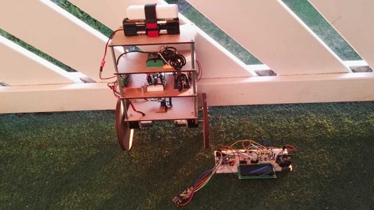
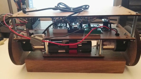
- 1. The physical structure of the robot is modified, so that the robot is much more robust and easier to control. The very early version is shown in the first picture, while the current version (2.0) is shown in the second picture.
- 2. An illustration of torque equilibrium of the robot is added.
- 3. A new program is written for PID tuning. This program visualizes the PID parameters. It's now much more comfort to tune the PID parameters.
- 4. An illustration of hysteresis characteristics of motor is added.
Step 1: List of Materials

Hardware Components:
I bought almost everything in Taobao, the largest online shop in China.
Remote Controller Parts:
One Arduino Nano microcontroller
One nRF24L01+ low power version module.
One LCD screen.
One joystick.
Four pushbuttons.
Five 220 ohm resistors.
One potentiometer.
One breadboard.
Some jumper wires.
Robot Parts:
One Arduino Nano microcontroller.
One nRF24L01+ low power version module.
One MPU6050 module, which has an accelerometer and a gyroscope.
One L293D motor driver IC.
One 12V AAA battery pack.
One power bank.
Some M3 bots and nuts.
Three small breadboards.
Some jumper wires.
Some Notes:
- Four pushbuttons are used for PID tuning and setpoint adjustment.
- The potentiometer is used for the adjustment of LCD's contrast.
- The power bank is used to power the Arduino. I plan to replace it with a voltage regulator in the next version.
Software Components:
- Arduino IDE. It's better to have the latest version, because the newest one has a tool called serial plotter. It's more comfortable to view the angle of the robot in graphic than numbers in serial monitor.
- CorelDRAW. It's used with a laser cutter to cut the frame.
- Sketchup. An open source software from google for 3D design.
- The source code and schematics can be found in GitHub.
Step 2: Understand the Physical Model

I have seen that many guys who managed to get his/her robot walk suggested to keep mass center as high as possible, by means of keeping the heaviest part on the top, thus it's "easier" to control. However, this is NOT true! On the contrary, the mass center should be kept as low as possible!
I put the battery pack on top of my robot 1.0. Besides I built four layers, and the distance between each layer is kept as large as possible. After countless frustrating trials and fails, I start to analyze the physical model.
The picture above shows the torque equilibrium. The goal is to keep the angle alpha as large as possible, in this way to robot is not easy to fall over, i.e. more stable. The torque of the motors is constant. In order to increase alpha, we should keep the mass center as low as possible, as well as the weight as small as possible.
Note:
- 1. As battery discharges, the output current is becoming smaller, therefore the torque of the motors gets gradually smaller.
- 2. The normal torque of the gear motor used in my project is 2kg/cm. But it's supposed to work at 12v. Since I use eight AA NiMH Battery, the total voltage is 8*1.2v = 9.6v. Therefore the torque of one motor in reality doesn't reach 2kg/cm, but approximately 1.6kg/cm.
Step 3: Design the Frame


The frame of the robot consists of four parts: layers, wheels, motor brackets, some M3 nuts and bolts.
I used a Zing 6030 laser cutter and CorelDRAW software to cut the layers and wheels. The material is 3mm HDF.
The motor brackets are designed using Sketchup software, produced by an ultimaker+ 3D printer.
There are four layers in the robot. In order to get a better control of the system, mass center should be kept as high as possible, and in the middle. Battery pack is normally the heaviest part, so it should be placed on the top layer of the robot. MPU6050 MUST be place in the middle of the layer! Otherwise It would be hard to control.
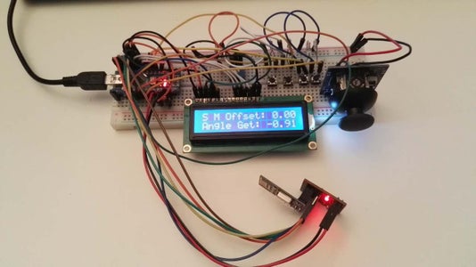
Step 4: Test MPU6050

The photo above shows the angle of the MPU6050 in Arduino's serial plotter.
The robot consists of a uC, a sensor module, a motor driver chip, and a transceiver. The remote controller consists of a uC, a LCD, push buttons, a joystick and a transceiver. It's better to test them one by one, than just assemble all the parts together and it simply doesn't work.
The MPU6050 has a 3-axis accelerometer and a 3-axis gyroscope. Accelerometer measures the acceleration. Accelerometer alone can be used to measure angle while it's kept still, because the gravity, always points to the center of the earth. Gyroscope measures the angle speed. The robot's angle is calculated from the acceleration and angle speed via complementary filter.
Step 5: Test Motor


Motor should have enough torque to drive the robot. I tried with two small high speed motors. However, them failed to move the robot because the torque is not big enough. Then I bought two gear motors, which have relatively large torque: 2kg/cm on average, low speed: 200 rpm without load. The speed can be compensated by using large wheels.
This motor requires 12v. H293D is used for powering the motors. H293D is a H-Bridge. The directions of the motors are controlled by the Arduino. Arduino also controls the speed of the motors via PWM.
Second picture shows the hysteresis of the motor. PWM is used to drive the motors. When the duty cycle of the PWM signal is low, the motor doesn't move because the average voltage is small. This nonlinearity adds diffculty to the PID control.
A part of this problem is solved by adding an offset to each motor, at which the motor just starts to turn.
After adding the offset, the robot doesn't have as many oscillations as before.
Other problem:
Each motor, even being manufactured at the same time, at the same location, with the same tool, the characteristics differs. Due to frictions, the speeds are slightly different, even though they work at the same voltage. Therefore the robot can't go straight, because the rpm of each motor is different.
Solution:
Add two encoders to each wheel, in order to measure the speed and direction of the motors. This will also be a closed loop control. In that case, the robot will be a cascade control system.
Step 6: Test NRF24L01+


There are mainly two versions of nRF24L01+ modules. If you use a high power version, pay attention: there are some problems with the high power version module: one is the SPI clock speed. If you use RF24 library and the high power module, replace the clock divider from SPI_CLOCK_DIV2 with SPI_CLOCK_DIV4. Another one is the power issue. Some modules are very sensitive to voltage change. Someone solved the problem by using a capacitor AND a voltage regulator. I did't verify the second issue.
Some options in the RF24 library:
To achieve the maximum range:
- set power amplifier to RF24_PA_MAX
- set data rate to RF24_250KBPS
- set payload size to be as small as possible
To achieve throughput:
- set power amplifier to RF24_PA_MAX
- set data rate to RF24_2MBPS
- set payload size to be <= 32 bytes
Besides, interrupt, acknowledge and CRC checksum calculation are enbaled by default.
Step 7: Assemble

After testing of each individual part, now it's time to assemble them together and make system tests.
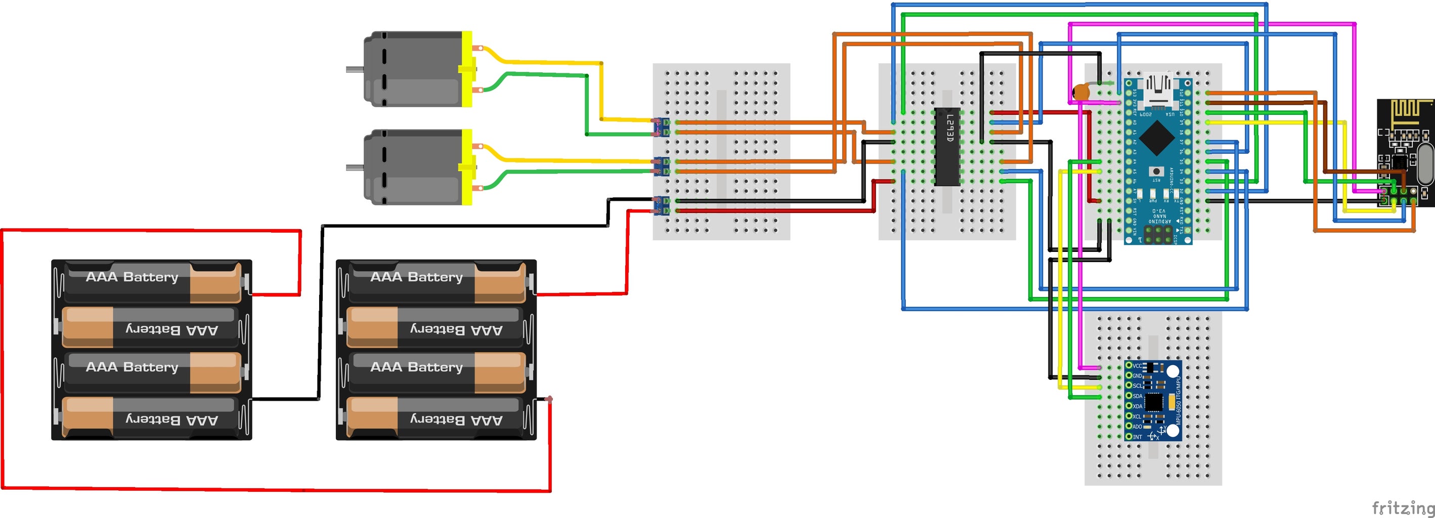
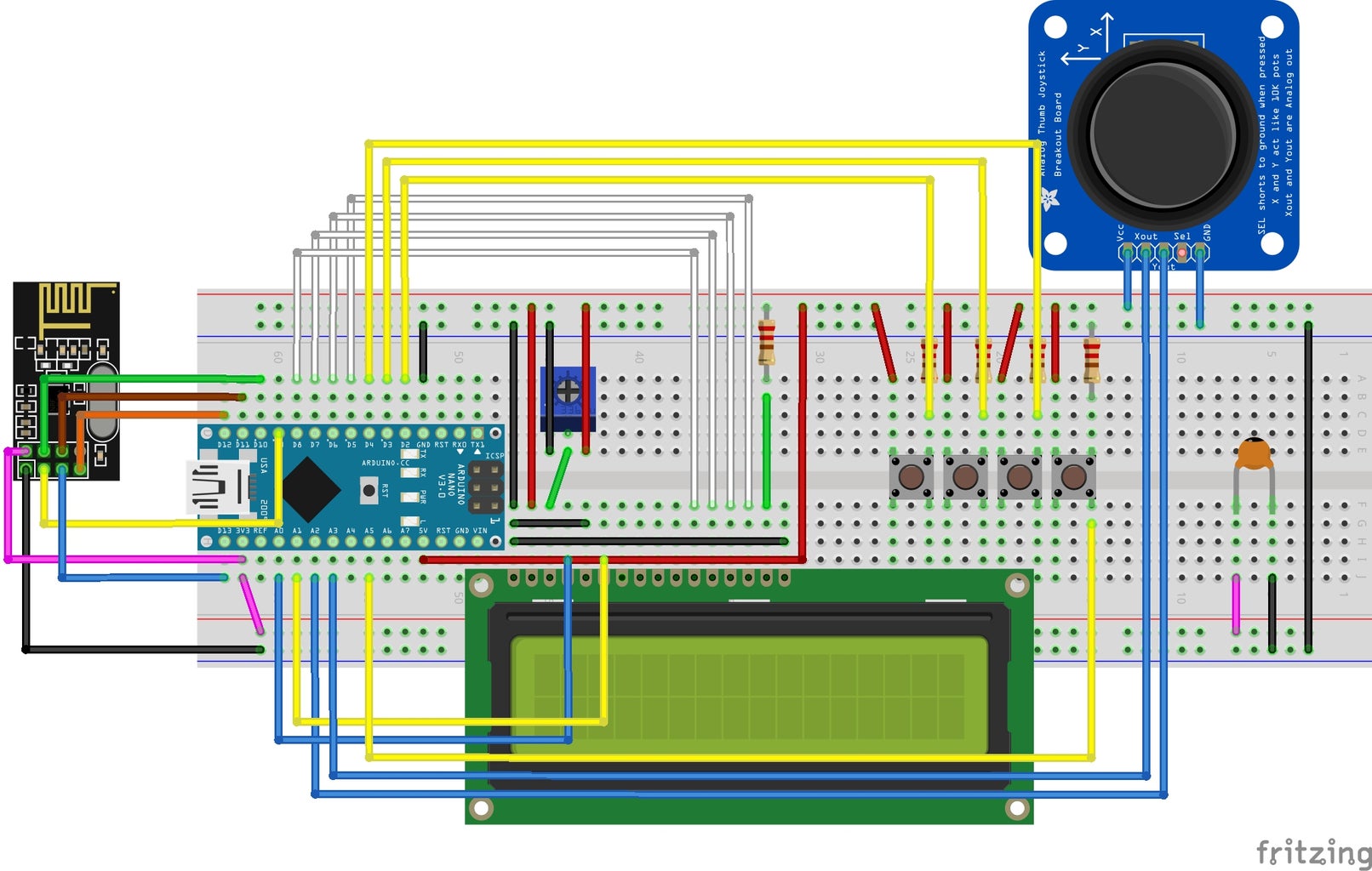
The connections are shown above. The drawback of using breadboard is that the connections are not very good. Some parts may work well one minute ago, but then doesn't work at all due to connection problem. I plan to replace the breadboards with a printed circuit board in future.
Step 8: PID Tuning - 1
This is the most important part. The goal is that the robot should have relatively high stability and very small overshoot.
Too large integral parameter results in instability and large overshoot; Too large derivative parameter results in very high frequency jitter.
Here’s how to tune the PID parameters:
- Step 1: Reset all parameters. Start to increase P parameter from zero, until the robot is fast enough to balance itself in the other direction.
- Step 2: Keep P unchanged. Increase I parameter gradually. If the robot starts to behave violently then decrease I parameter.
- Step 3: Keep P and I unchanged. Increase D parameter gradually. If the frequency of the jitter is very high then decrease D parameter.
- Step 4: Restart from step 1 if it doesn’t meet the goal.
Update:
I've written a PID tuning program with Qt and a third party class called QCustomPlot. Now it's much easier and ituitive to tun the PID parameters.
The second video shows how the robot overcomes disturbance. After some overshoots, the actual angle gets very closed to the desired angle.
Below is the source code of PID calculation.
pPart = pidValue.proportionalValue * angleErrorNew;
iPart += pidValue.integralValue * angleErrorNew;
dPart = pidValue.derivativelValue * (angleErrorNew - angleErrorOld);
Step 9: PID Tuning - 2


Update:
- The first graph shows that the robot can keep itself still for a relatively long period.
- The second graph shows that too large P causes oscillation. But the pattern always matches the current angle, because P represent the current state.
- The third graph shows that too large I causes oscillation and instability. The phase of the I is behind P, because I accumulates the errors over time, it represents the past.
- The fourth graph shows that too large D causes high frequency jitter. Although it doesn't cause instability issue, it brings high frequency noise to the robot. D predicts the tendency, it represents the future.
Step 10: Add Commands to Control the Robot
Robot can not only stand, but also walk. By changing the setpoint of the robot, the robot can move forward or backward. By changing the rotation of one wheel, the robot can turn clockwise or counterclockwise.


