

Introduction: Servo Steering Robot for Arduino


组装视频网址:https://youtu.be/ulTM1uV1Bvg
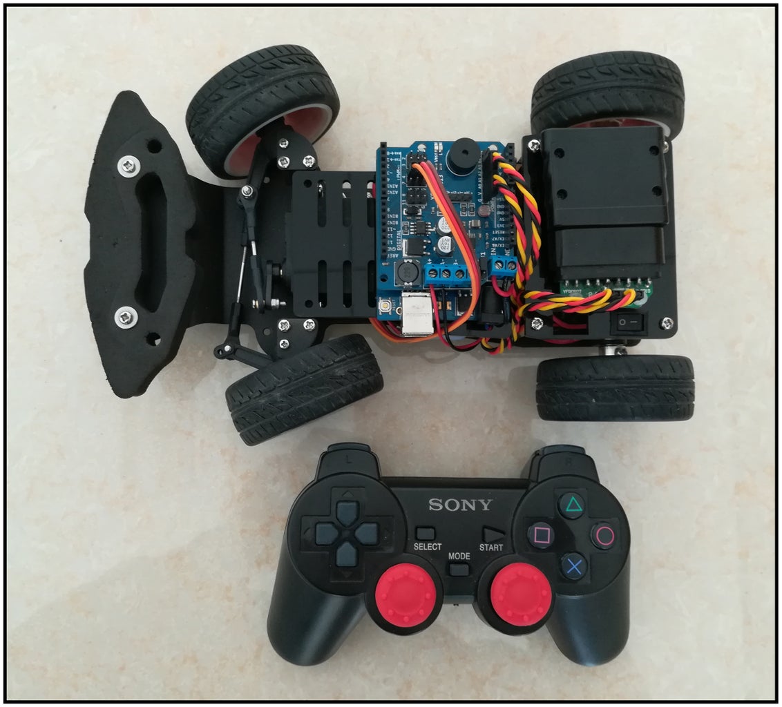
这款车基于arduino平台设计,核心是Atmega-328p,可以实现前轮转向、后轮驱动等功能。
如果你只是一个人玩,只需要使用无线模块;如果你想实现其他功能,可能需要添加其他传感器或硬件。
Step 1: The Required Parts


When you want to have a controlled by the steering gear to car,You need the following parts:
- Arduino:arduino Compatible version(blue bird)
- Motor driver board :PM-R3
- Power battery :7.4V -18650
- Remote control part :PS2(of course, you can also use bluetooth control)
- Dupont line :a small amount of
- Of course, you will also need the car frame(include motor , servo)
PM - R3 module integrated I/O expansion and motor drive
- Dual motor output
- Power input
- Digital I/O (S V G)
- Analog I/O
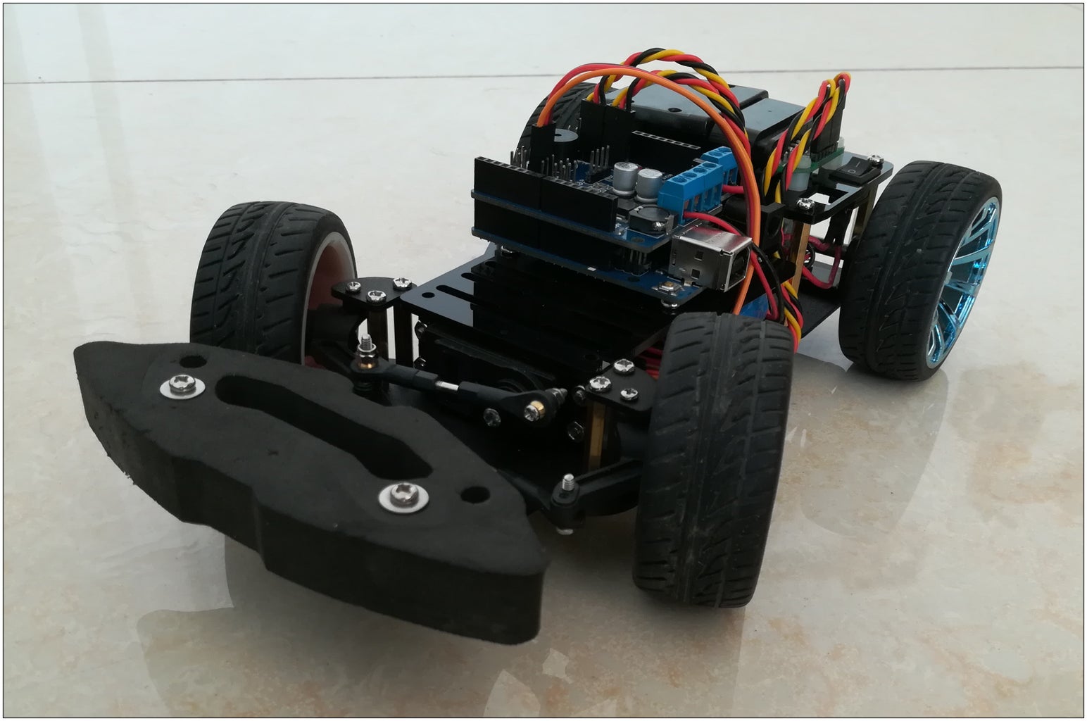
Step 2: Install the Frame(Drive Part)


First we install the drive part, drive motor is JGA25-370, through a gear reduction drive axle and wheel forward retreat, the motor shaft gear is big, because after the drive shaft and support distance is small, can't install big gear, but overall still slow.
Rear wheel bearings with flange bearings, to prevent the gear sliding down when running, you can also reduce power consumption.
- motor bracket x1
- 370 high speed motor x 1
- Gear A pair
- 5mm shaft x 1
- Flange bearing x 2
- 5mm coupling x 2
- M3 * 8 mm screw and nut x 5
Step 3: Front Steering Parts


Before turning part adopts the design of the RC, also with most of the accessories, such as the wheel parts;In order to keep the wheels of flexible, both inside and outside the bearing with installation.MG996R metal as power steering, the steering gear with two L shaped bracket should be fixed to the chassis,Servo motor connecting rod when installation, please ensure the steering Angle are already owned by (1.5 ms), the switch to the scope of the convenient adjustment and in the late.
- M2.5 * 12mm screw and nut x 1
- M3 * 8mm screw and nut x 4
- M4 locknut x 2
Step 4:

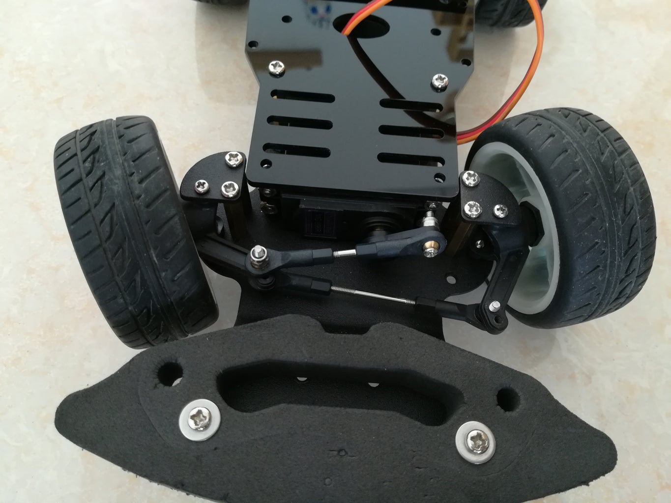

Will be assembled to part and servo motor is fixed to the turf,Can't tighten the screw fixed to a cup, it will lead to can't turn, is likely to burn out the servo motor and single chip microcomputer;Using the connecting rod connects two front wheels, and connected to the servo motor on the rudder Angle;Servo motor is fixed with the M3 * 8 mm screw and nut, fixed with M2.5 * 8 mm screw to cup, copper column side is 2 M3 * 8 mm screw.
- M2.5 * 8mm x 5
- M2.5 * 20mm x 1
- M3 * 8mm x 10
- M3 nut x 4
- Copper pillar x 4
Step 5: Connection Part


Motor driven extension board can be used directly, and the mainboard without other wiring,just need to PS2 receiver and servo motor upon receiving the I/O port expansion board, the power input port in the VCC & GND expansion board, motor output in A + and A -,another motor output in B+ and B-.So, we can control the two dc motors, here we only need one interface.
Servo Pin : I/O 4
PS2 did a transfer board, convenient wiring, reverse connect protection, recommend the following connection here
PS2 Pin :
- GND : GND
- VCC : +3.3v or +5v
- DAT : A0
- CMD : A1
- CS : A2
- CLK : A3
Power input VIN & GND, 3-9 v voltage range.
Step 6: Code
Through the modification of the program to achieve the robot's walking, motor control forward and back, servo control direction; program contains PS2 control, Bluetooth control and follow-line.
The program should be changed to the latest version to match the new PM-R3.
Old code see PS2_old


