

Introduction: Simple IR Module - Object Detection


Infra Red or IR sensor:
•It is a sensor which uses IR rays to emit and receive and detects movements accordingly.
•It has an IR emitter and a receiver (photo diode).
Applications
- TV remotes
- Obstacle detectors
Components required :-
- Bread Board
- 7805IC - 5 V regulator
- A 9 V battery
- IR emitter
- IR receiver (PhotoDiode)
- 2 * 150 ohm resistors
- LM 358 IC
- BC547 or SL-100 transistor
- LED
- Connecting wires
Theory behind working:-
IR emitter:
This is an infrared emitter diode. Infrared is invisible to naked eye but it can be seen using a mobile camera. An IR LED, also known as IR transmitter, is a special purpose LED that transmits infrared rays in the range of 760 nm wavelength. Such LEDs are usually made of Gallium arsenide or Aluminum gallium arsenide. They, along with IR receivers, are commonly used as sensors.
PhotoDiode:
A photodiode is a black colored diode which produces current in MilliAmperes range. It has black colored coating which is a filter to pass only IR rays to the diode.
Make your own IR module by following 6 simple steps:-
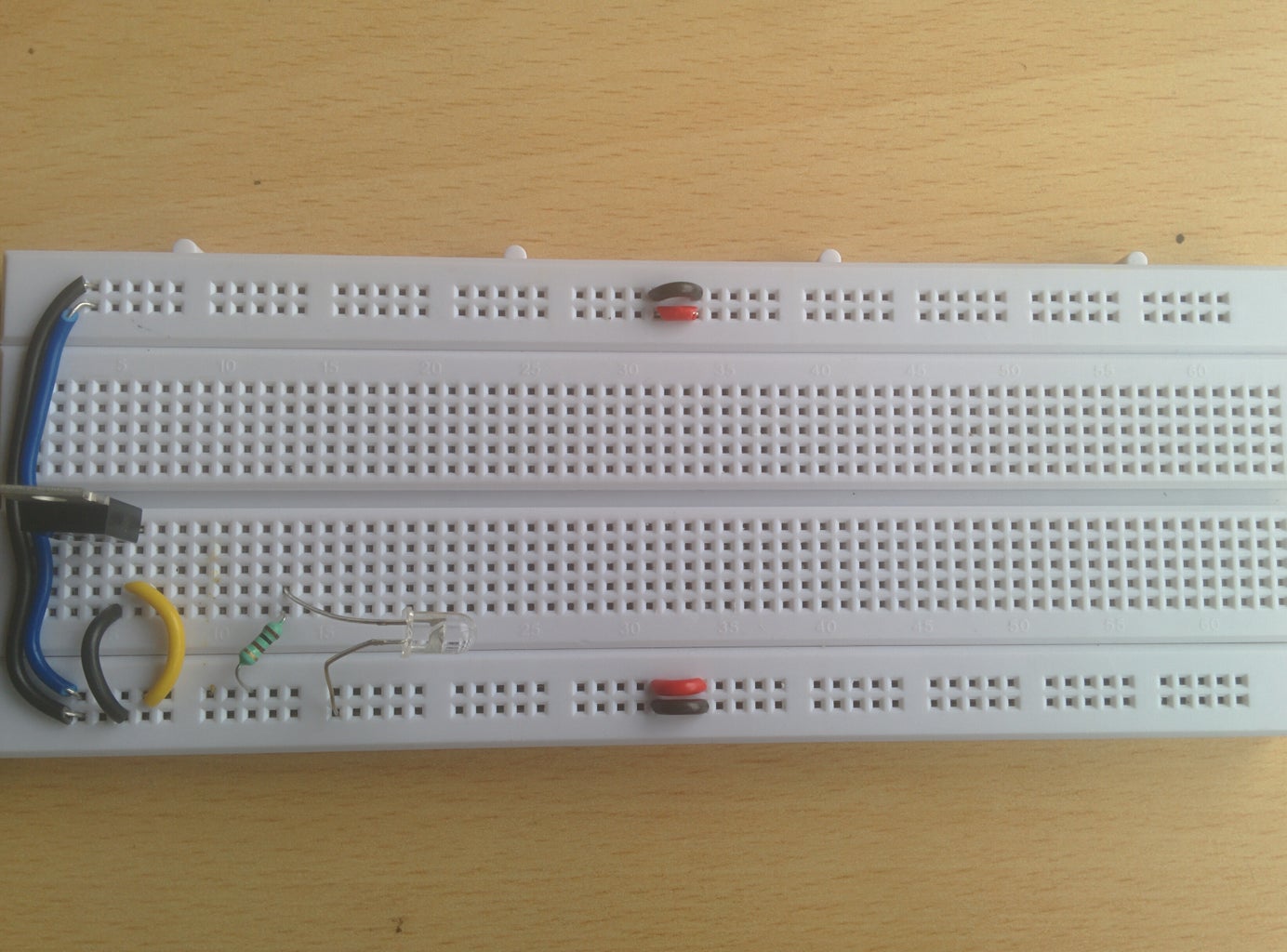
Step 1: Bread Board Connections

Plug the 7805 IC into the bread board. According to the pin numbers of 7805 - Pin1 is input, Pin2 is GND and Pin3 is Output when the hump of the IC is facing you. Give the input of 9 V across P1 and P2. Take the output across P3 and make the power rails with a 5 V supply. (More details regarding the bread board connections is available on the net).
Step 2: IR Emitter Connection
Take IR emitter and connect it to 5 V supply through a 150 ohm resistor. Ground the negative terminal of the IR emitter.( Make sure positive terminal is connected to 5 V through a 150 ohm current limiting resistor).
Step 3: LM358 - Connections


LM358:
It is a low power OPAMP IC which can amplify low level signals to readable high levels. It works on 5V supply and can give a max. Saturated output of ~4V.
1. OUT1: Output pin of the opamp1.
2. IN-: This is inverting input to the OPAMP1. Whatever input given, gets inverted to negative The IC has two set of Op Amps. Pin description is as follows: Value. Then output will be –ve. When this pin is used, the IN+ should be grounded when used in open loop mode.
3. IN+: This is non-Inverting input to the opamp1. The output is +ve when an input is given to this pin. When this pin is used, the other input pin, ie, IN- must be grounded when used in Open loop mode.
4. VCC: This is the main power supply to the IC. It can be 3V to 32V max. Depending upon supply voltage, the max output voltage varies. If, 5V supply, output can be ~4V. To this terminal, Positive of battery or source is connected.
5. GND: This is where we need to connect Negative terminal of the battery. If we use the IC for AC signals, then instead of calling it GND, we call it –VEE.
Connect Pin8 to 5 V rail and Pin4 to ground rail as shown in the picture. Now ground non-inverting terminal (Pin3). Align the IR receiver with the transmitter and connect the IR receiver (PhotoDiode) positive to the ground rail so as to reverse bias the photo diode whose current generated is called as Dark Current , and connect the negative terminal to the inverting pin(Pin2) of LM358.
Step 4: Transistor As a Switch

We make use of transistor as a switch, where in, Base terminal is used to give input and collector terminal is used for supplying Vcc. So when base input is high, the transistor turns on and supplies the load with VCC. It is very helpful to use transistor as switch as we can give a small base input and supply a very large current to the load. The load in our case is Diode.
We can use either BC547 or SL-100 for this purpose, both works fine.
Since we need to give the input through the base of the transistor, connect the output(Pin1) to base of the SL-100(in our case). Space apart the collector and emitter as shown in the picture.
Step 5: Indication of Detection Through LED

Connect the collector of the transistor to the 5 V rail and connect the positive terminal of LED to the emitter of SL-100 through a 150 ohm resistor. Also plug the negative terminal of the LED into the ground rail of the bread board.
Step 6: Working of Obstacle Detector Circuit

The IR LED1 is connected to a 5V supply using a 150 OHM resistor. This resistor acts as a current limiter and allows only 20mA current to the Diode. That is the current required by LED to turn ON and glow.
When the photodiode receives IR rays directly or reflected, it produces leakage currents of order of few mA. We always use photodiode in reverse bias mode as current proportional to the intensity of light is produced. If we use photodiode in Forward bias, then the diode will just act as switch. This leakage current is amplified by LM358. The Output of the op amp is 4V but the current it produces is just 100mA which is not sufficient for a load (Here LED). So we connect its output to a transistor base input. The transistor then supplies required current directly from the Power supply.
For more sensor related circuits - Ping a request through mail at youngengineerborn2016@gmail.com
Visit my youtube channel here =>> Young Engineer
New Instructable soon on ==> GCAR v2.0 Gesture controlled automated robot.
Stay rigging! :)
Eat Sleep Rig-up Repeat.


